IO Manual
Shenzhen NuPhy Technology Co., Ltd.
NuPhy R&D Department
Last updated on November 18th, 2024
Mode Selection Page
Navigation Bar
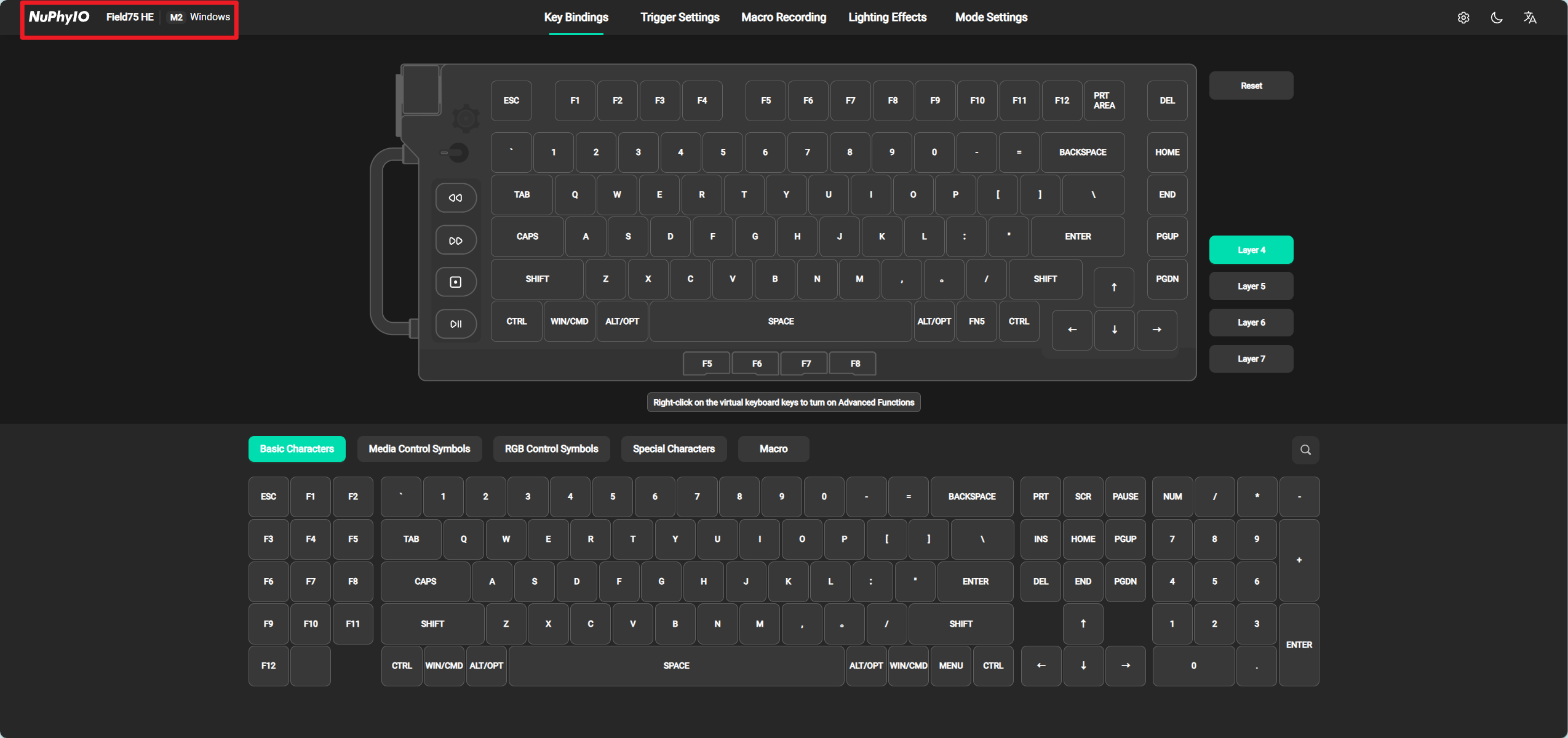
Information Display
This mainly displays the current device name and the mode in which the device is currently located.

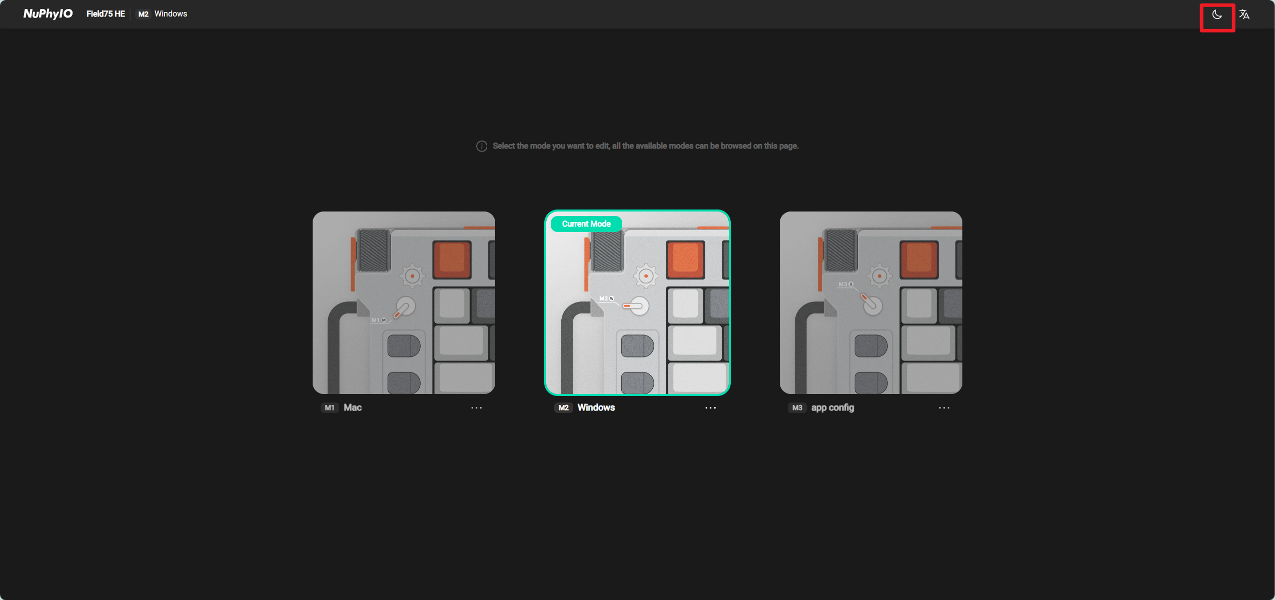
Theme Switching
Click to button between bright/dark themes. After setting, the next time you open it, the selected theme will prevail.
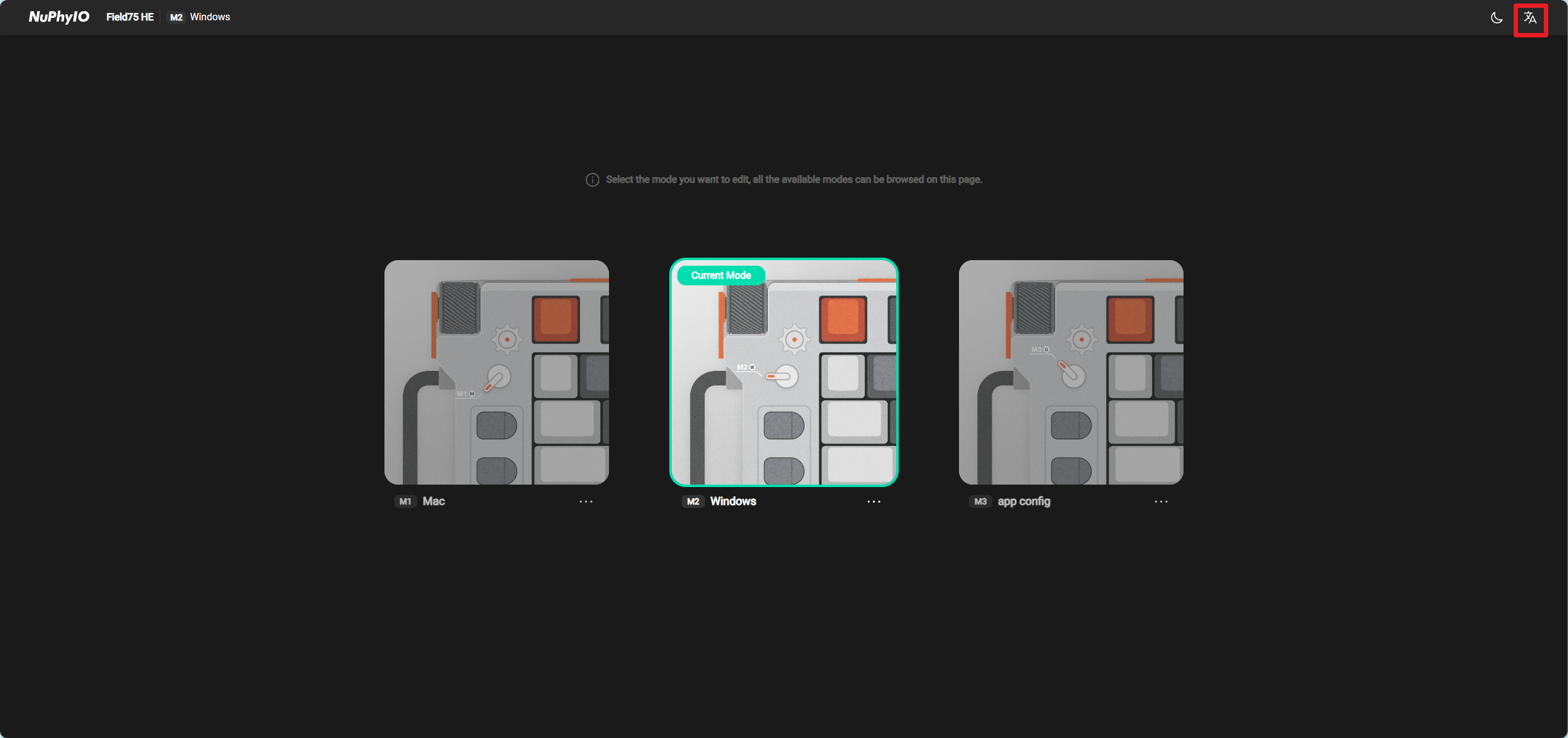
Language Switching
Click to button the language displayed by NuPhyIO. After setting, the next time you open it, the selected language will be used as the reference.
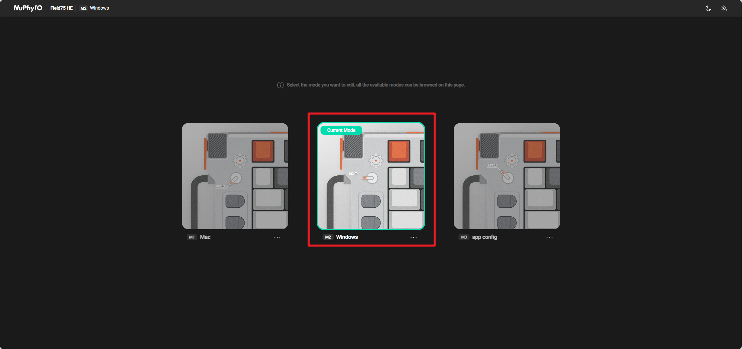
Pattern Card
Clicking on the card will take you to the settings editing page for this mode, which currently only supports entering the current mode of the keyboard for editing.
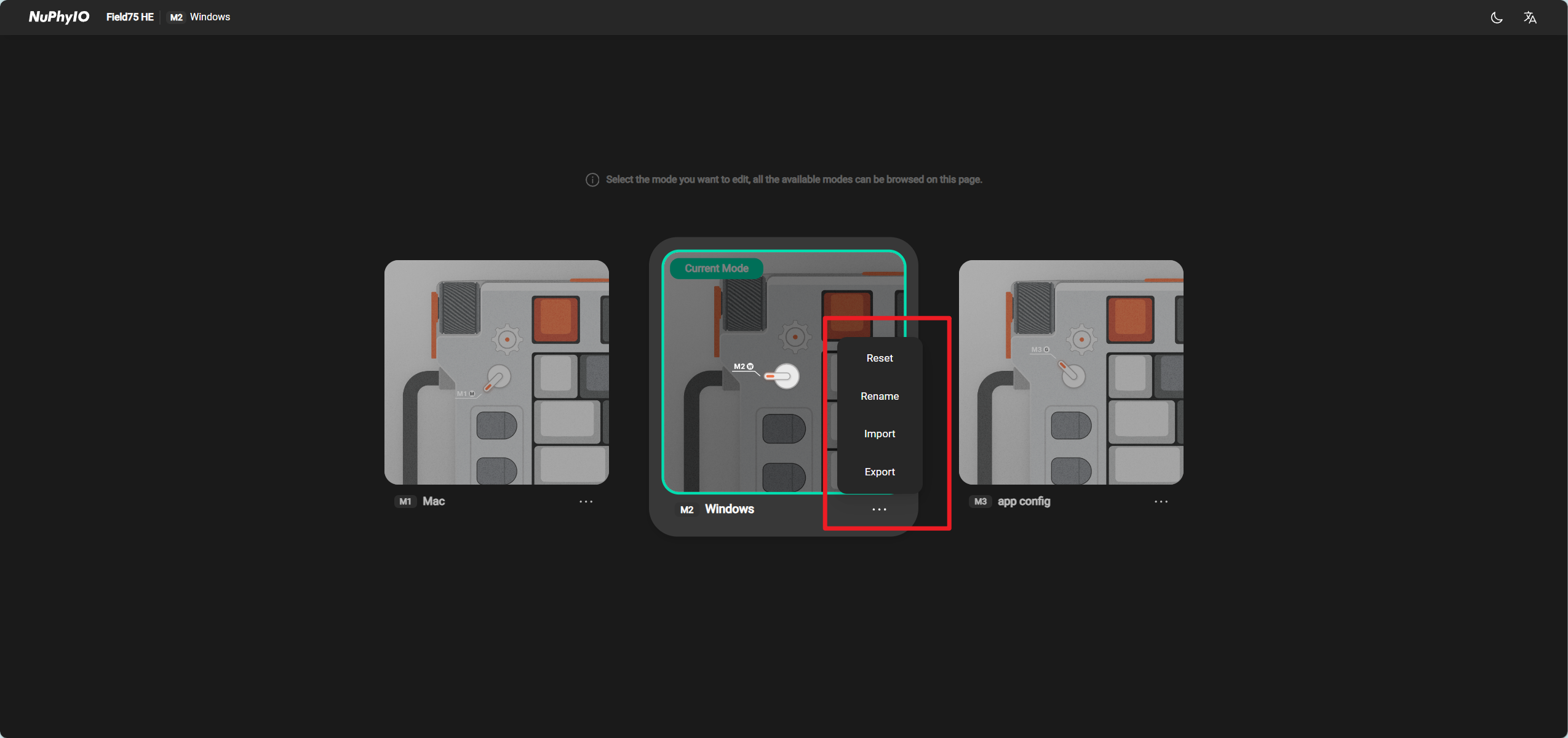
Click the ellipsis in the bottom right corner of the mode card to perform operations such as renaming, restoring default, and importing/exporting on the current mode in the pop-up box.
Key Bindings Page
Navigation Bar
Information Display
This mainly displays the current device name and the mode in which the device is currently located.
Click on Device Name to return to the Mode Selection Page.
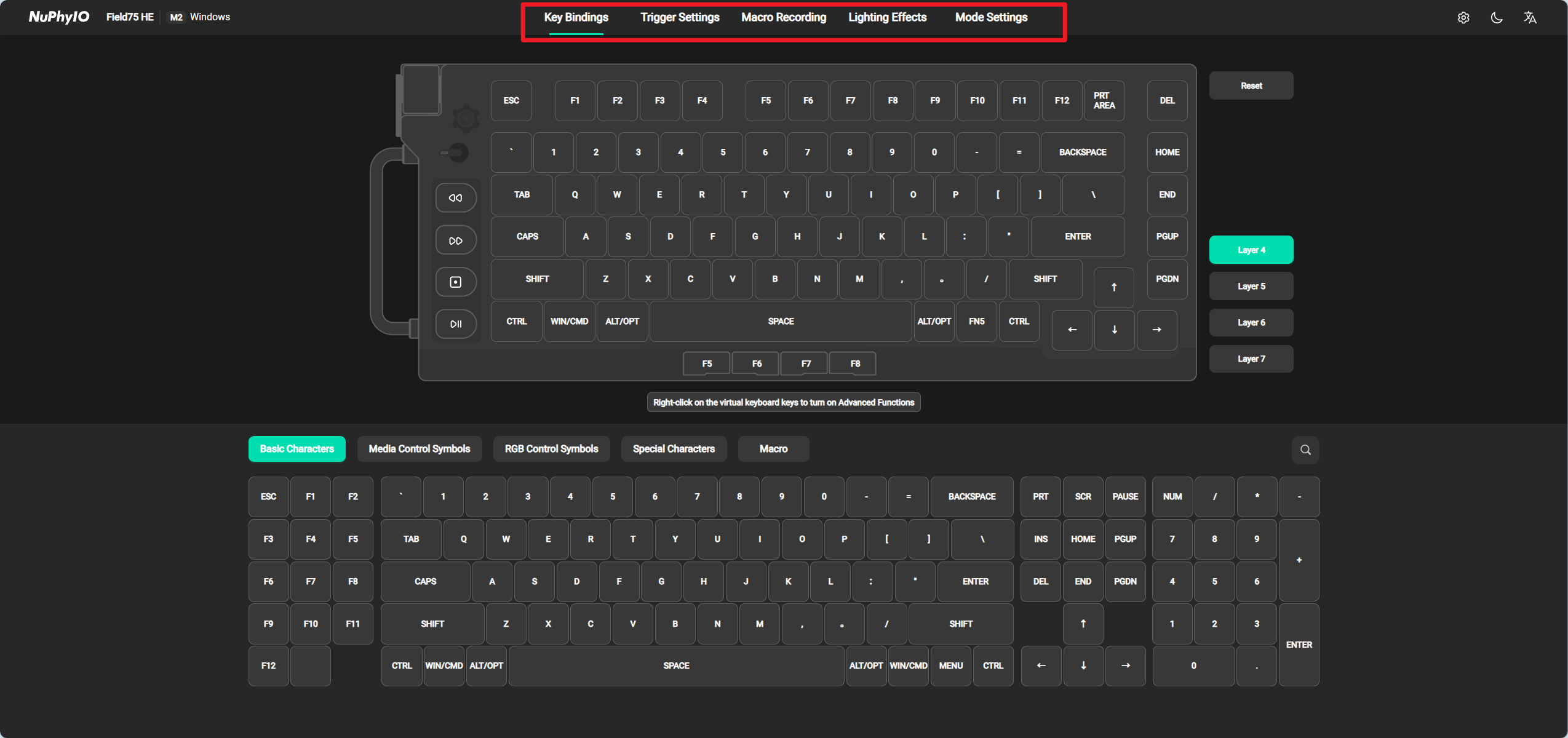
Title Bar
Click on any title in the title bar to enter the corresponding interface.
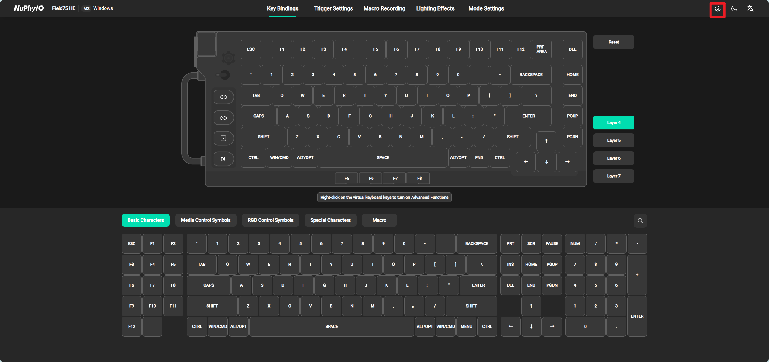
Keyboard Settings Page
Click the Settings button to enter the keyboard settings page.
Page Functionality
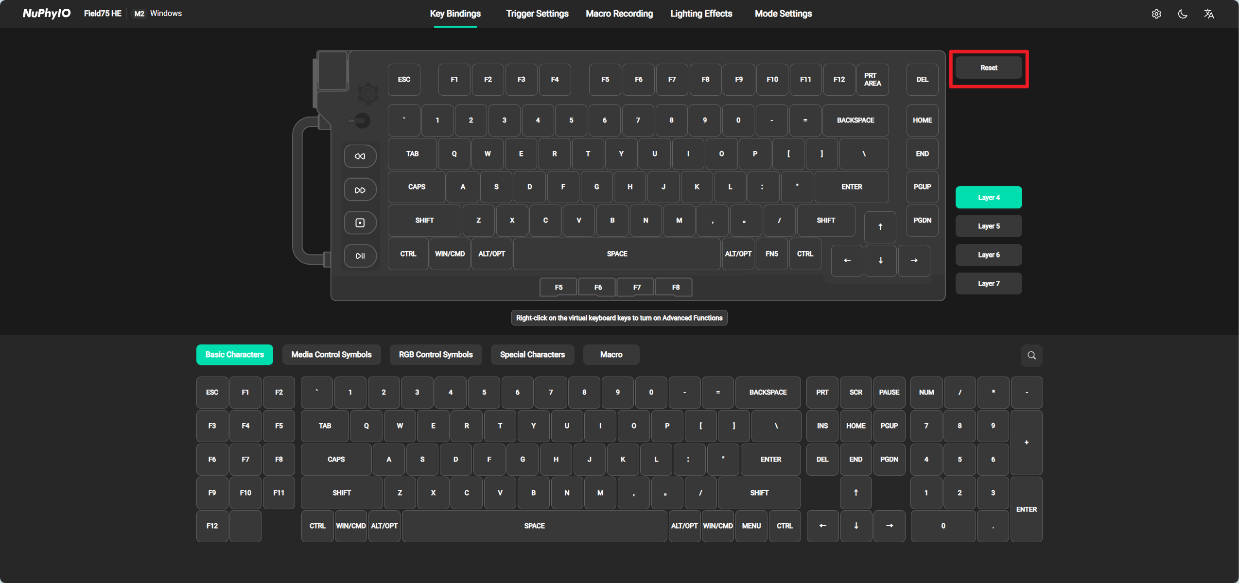
Restore Default
Click the Reset button to restore the factory settings of all keys in the current level.
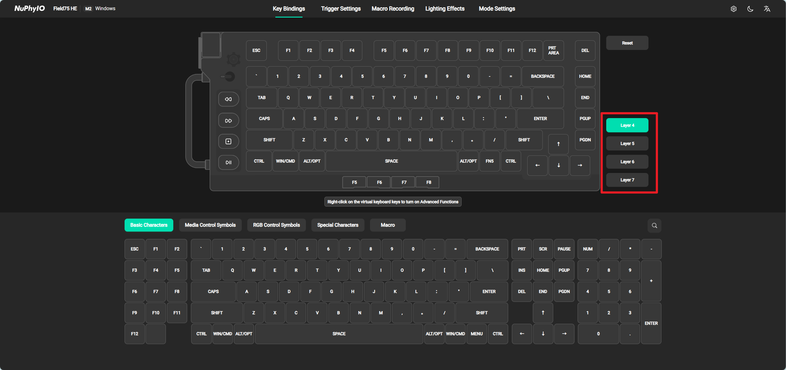
Layer Switching
Clicking on a button at a certain Layer will display the Switchs bound to that Layer. Each Layer has a corresponding number, and you need to hold down the corresponding FN key to use the keys bound to this Layer. For example, if you have bound the A key at a certain position in level 5, you must hold down FN5 and then press the key at the position where the A key is located to trigger the A key function.
It should be noted that each mode has a default level, which is arranged above all levels. For example, in the following figure, level 4 is the default level, and the default level does not require pressing any FN key to trigger the functions bound in the level.
Normal Key Change
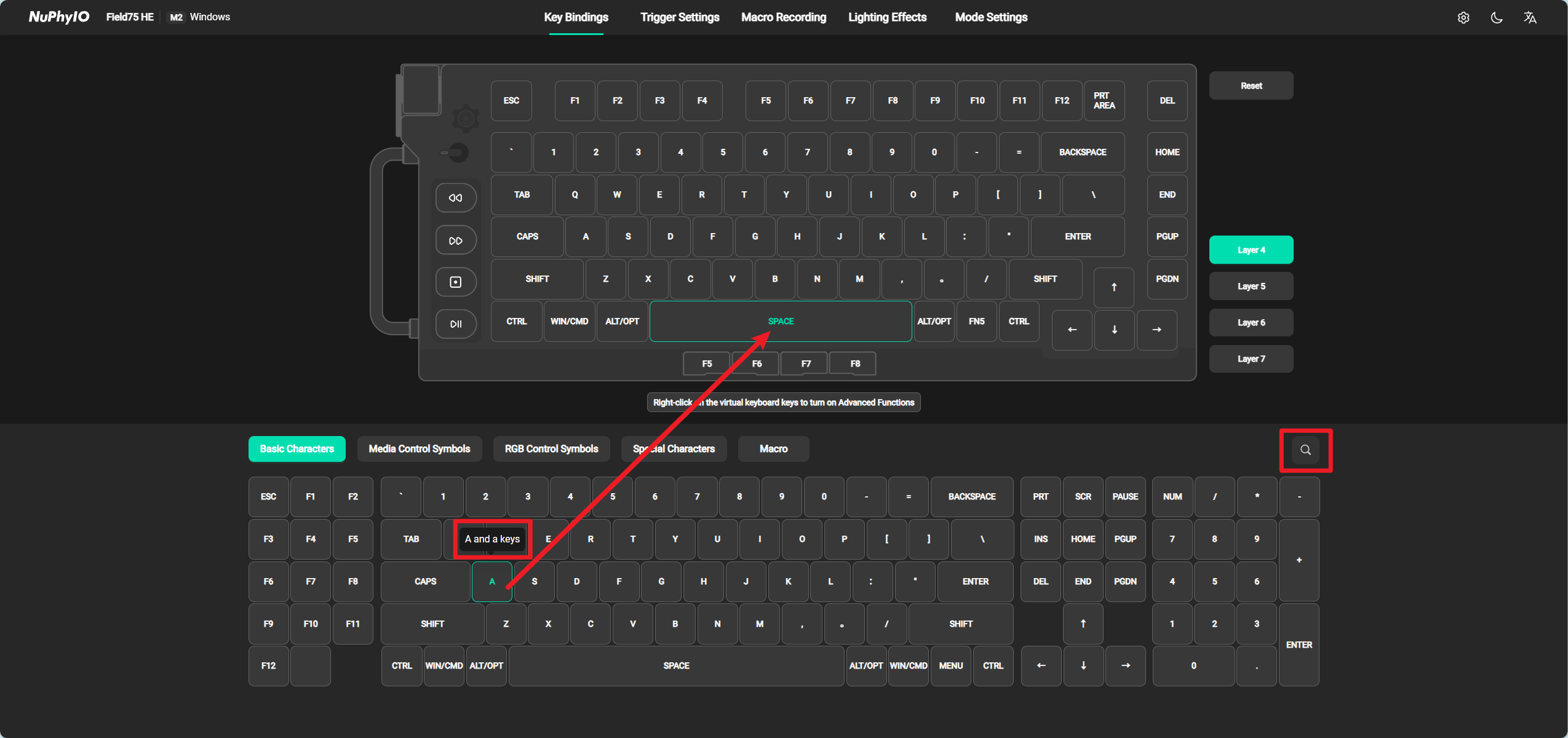
Normally, to change a key, you only need to first find the desired position on the virtual keyboard, select the position with the left mouse Switch (the border of the selected position will turn green), and then find the character you want to change under the virtual keyboard. Click on the character to make the change. In addition:
-
Support hovering the mouse over any character to view and explain its related explanations.
-
Support entering characters or their explanations to search for the desired content.
-
Due to style issues, some characters cannot be fully displayed, which can be viewed in its related explanations.
-
If you have any other characters you would like, please send them to our email and we will update them as soon as possible feedback@nuphy.com .
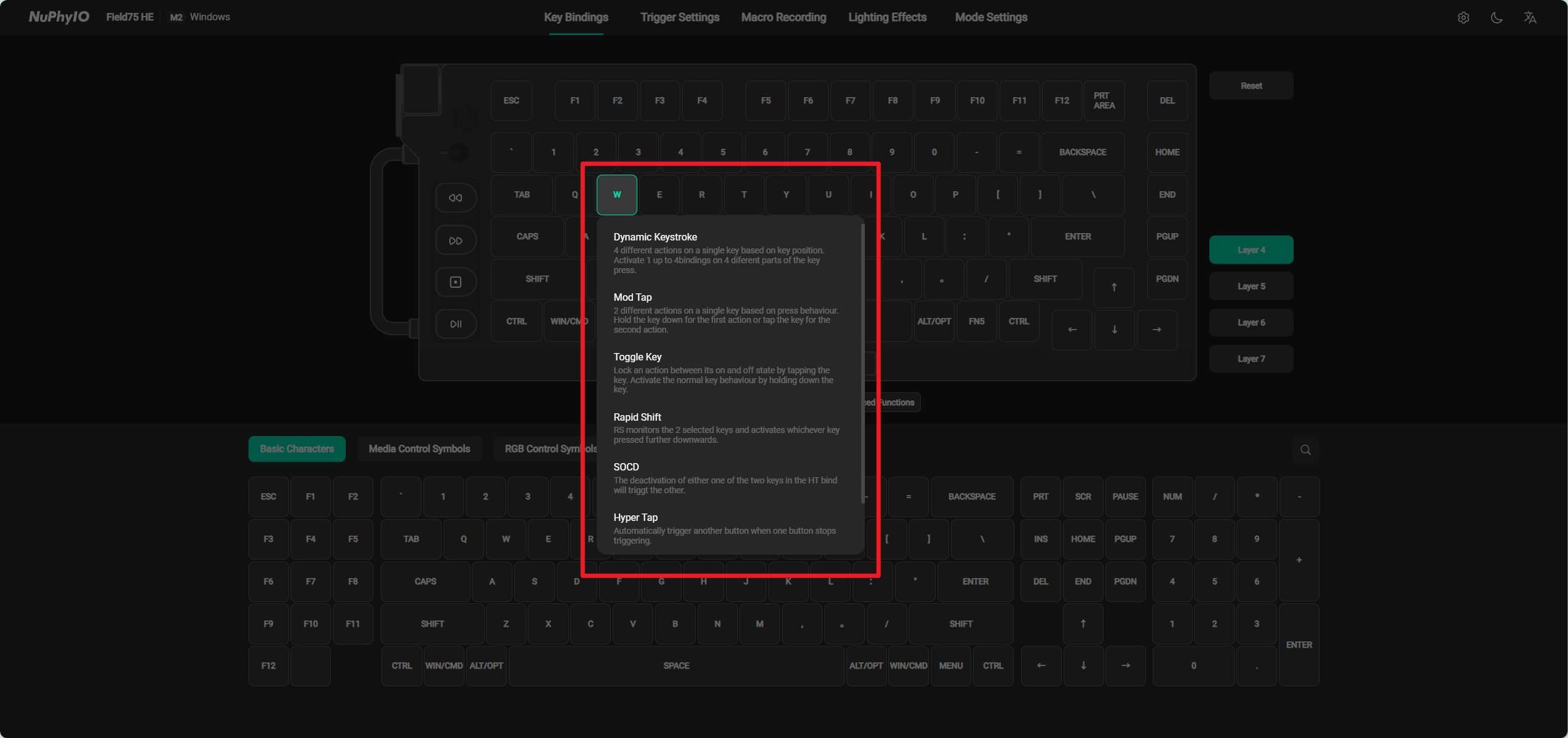
Advanced Functions
Right click on the key on the virtual keyboard that you want to change to an advanced function, and you will be able to turn on the advanced function. In the pop-up window, you can choose from six advanced key change functions: Dynamic Keystroke (DKS), Mod Tap (MT), Toggle Key (TGL), Rapid Shift (RS), SOCD, and Hyper Tap (HT). In addition, you can also choose to restore this Switch to its default function in the pop-up window.
Dynamic Keystroke (DKS)
Under the Dynamic Keystroke (DKS) function, a single key can be bound to four functions, and after binding, you can customize when they are triggered. For example:
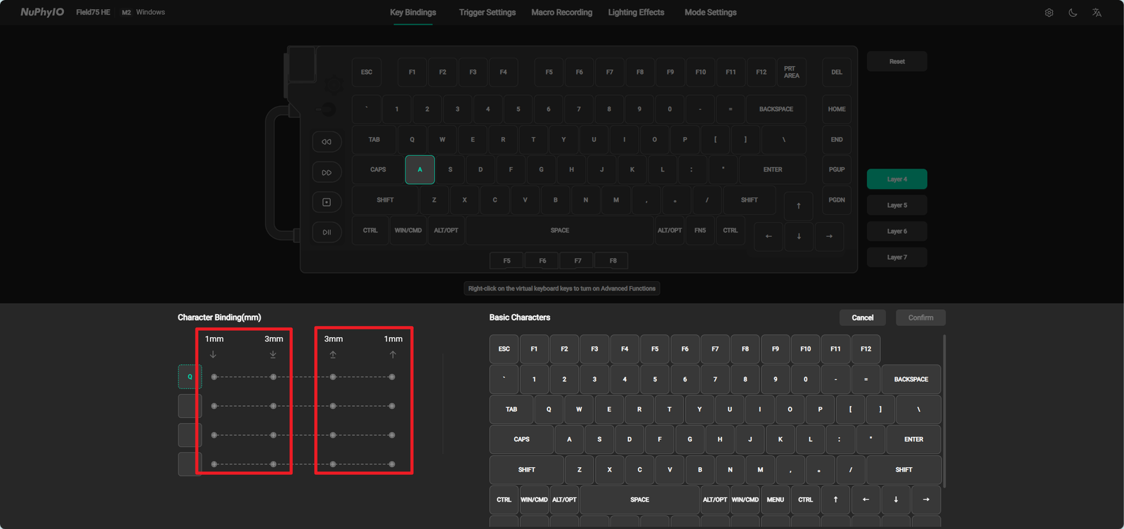
- Select a position in Character Binding, and its border will turn green when selected. Select the character you want on the right again. If you select the wrong character, you can directly reselect it or move the mouse to the corresponding character in Character Binding to delete it.
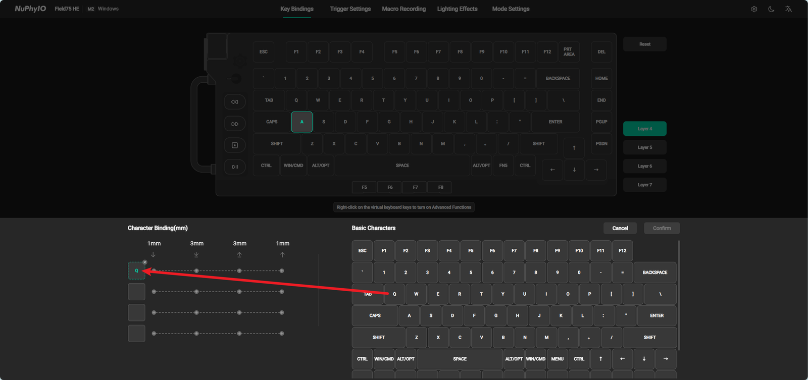
- Support setting when to trigger the current character in Character Binding. The first two columns represent triggering when pressing 1mm or 3mm, and the last two columns represent triggering when lifting 1mm or 3mm after touching the bottom.
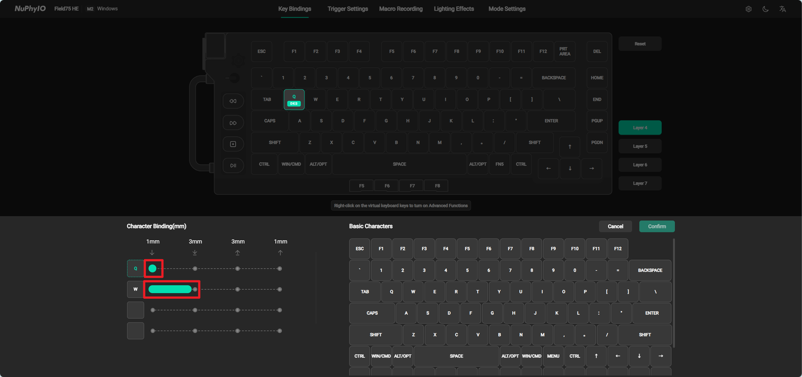
- Support setting the trigger form of the current character in Character Binding. When a certain position is selected, it will only trigger once. When this position is selected and dragged to the next position, it will continue to trigger within this key range. For example, the setting in the following figure represents that pressing this Switch 1mm will trigger Q, and pressing this Switch between 1mm and 3mm will continuously trigger W. After setting up, clicking the Confirm button will display the DKS symbol.
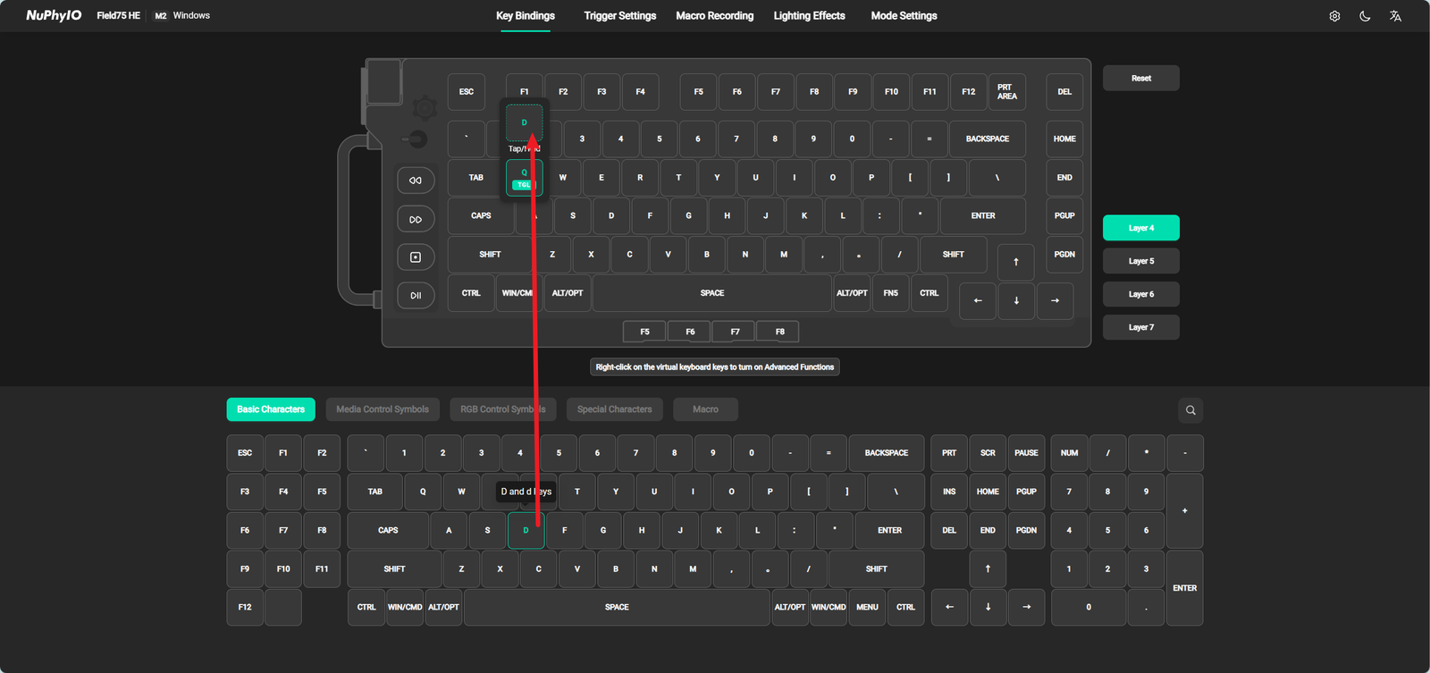
Mod Tap (MT)
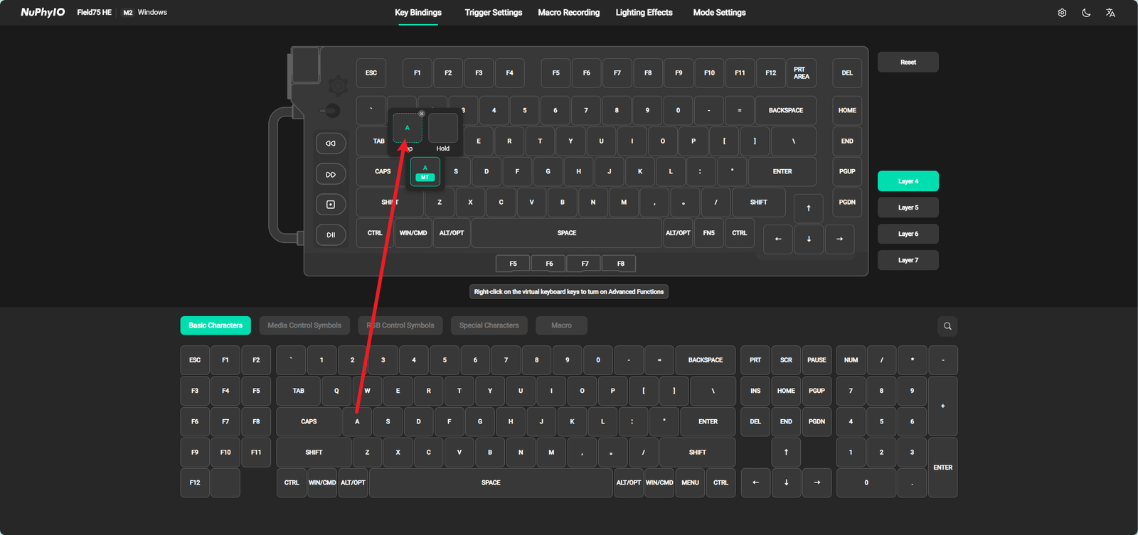
Under the Mod Tap (MT) function, a single Switch can achieve two functions, one when held down and the other when clicked. For example:
- Select a position in Character Binding, and its border will turn green when selected. Select the character you want on the bottom again. If you select the wrong character, you can directly reselect or move the mouse to the corresponding character in Character Binding to delete it.
-
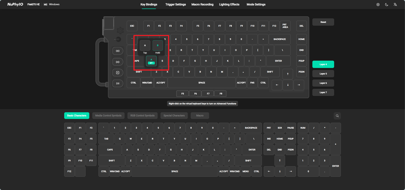
After selection is complete, clicking and holding this Switch will display different characters. And this Switch will display the MT symbol. For example, in the A key shown below, clicking it will display A, and long pressing it will display B.
Toggle Key (TGL)
Under the Toggle Key (TGL) function, it is possible to continuously trigger by clicking the Switch, and stop triggering by clicking the Switch again (note: long pressing the Switch will continue to trigger, and releasing the Switch at this time will stop triggering).
-
Select the position in Character Binding, and its border will turn green when selected. Select the character you want on the bottom again. If you select the wrong character, you can directly reselect or move the mouse to the corresponding character in Character Binding to delete it.
-
After the selection is completed, the program will automatically save. Clicking this Switch will continuously trigger the bound characters. And the TGL symbol will be displayed on this Switch.
Rapid Shift (RS)
Under the Rapid Shift (RS) function, it is possible to bind two keys together, and when both keys are held down simultaneously, only the key with a higher key path is triggered.
- Firstly, you need to select two Switchs and bind them together. For example, in the following figure, the A and B keys are bound together. Assuming their Actuation Point is 1mm, when A presses 1.5mm, the A key will continue to trigger. At this time, if the B key is pressed 1.6mm, only the B key will be triggered and the A key will stop triggering. Similarly, if the B key is released to 1.4mm, only the A key will be triggered and the B key will stop triggering.
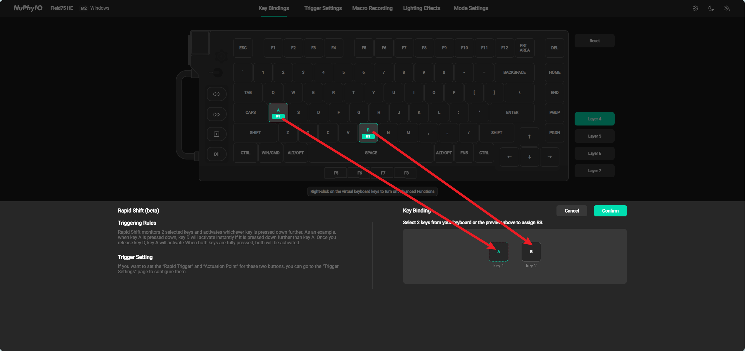
- After binding two keys, you can go to the Trigger Setting page to set their trigger parameters. The two keys bound together can only modify all trigger parameters at the same time.
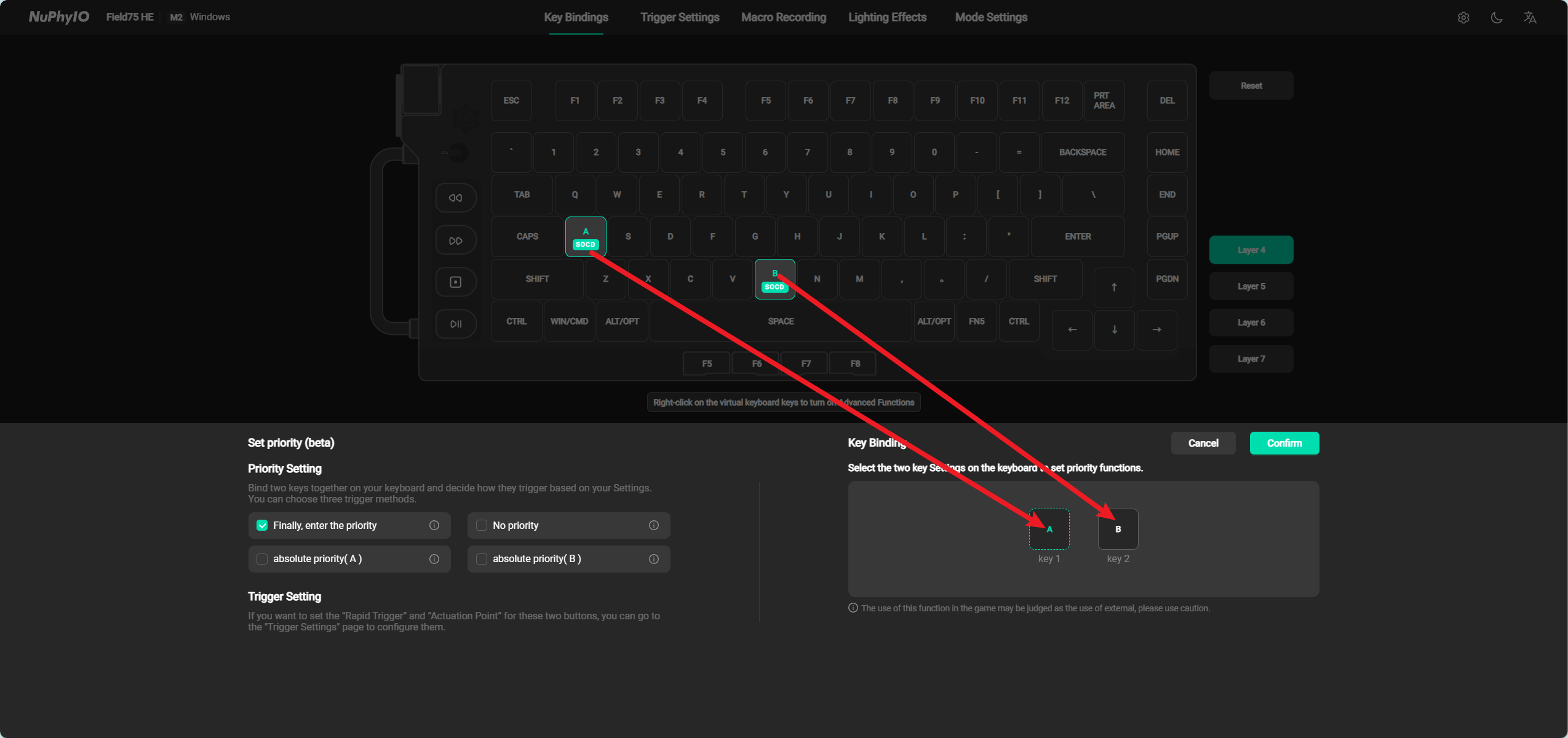
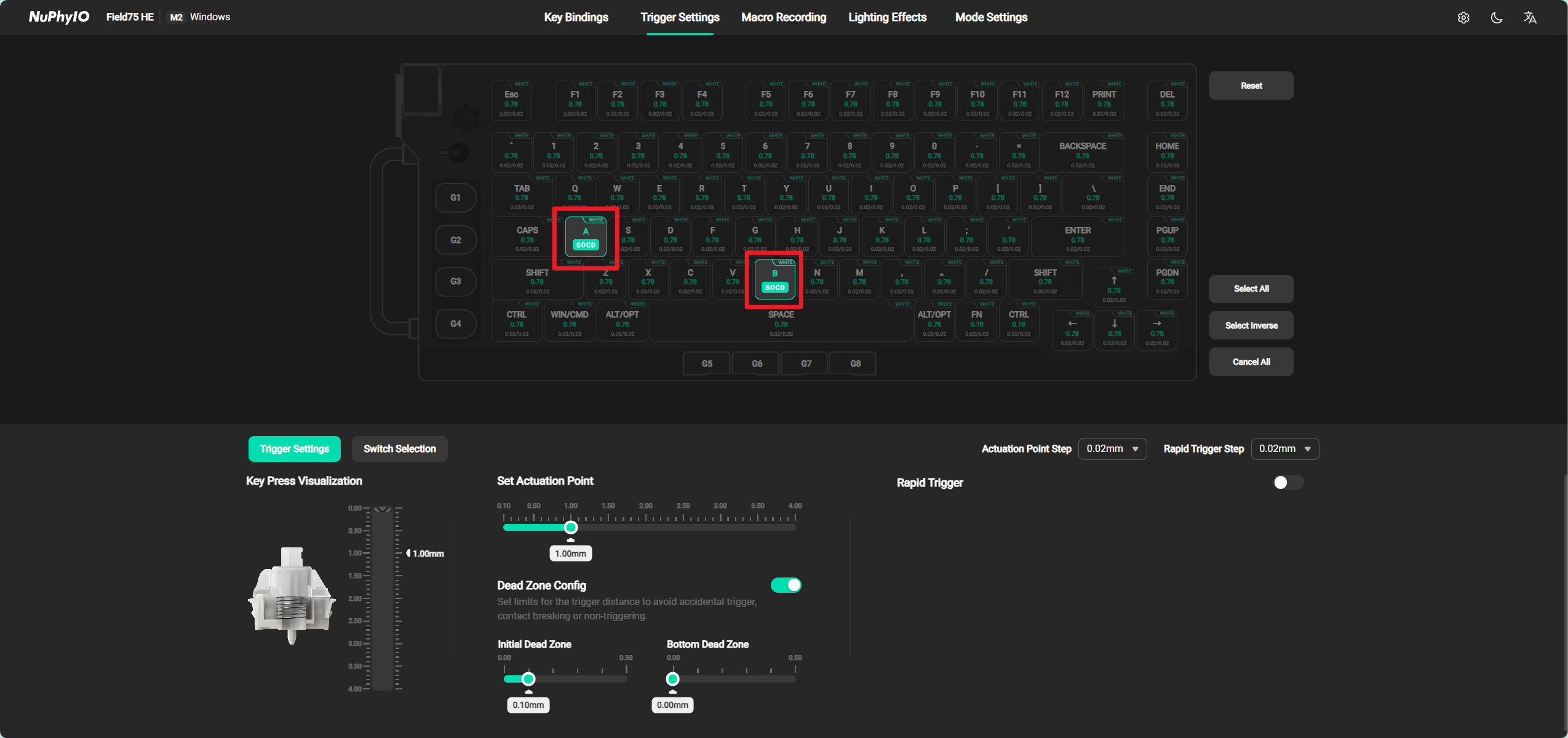
SOCD
Under the SOCD function, it is possible to bind two Switchs together, and when both Switchs are held down, the user can select which one will trigger them through their own settings.
The SOCD function requires setting priority first, and there are three priority options to choose from:
-
Last input priority: When both Switchs are pressed and exceed the set Actuation Point, the last pressed Switch will overwrite the first Switch. For example, bind keys A and B to the SOCD function and set their triggering stroke to 1mm. When key A is pressed more than 1mm, key A will continue to trigger. When key B is pressed more than 1mm, key B will only be triggered and key A will stop triggering.
-
No priority: When both Switchs are pressed and exceed the set Actuation Point, neither Switch will trigger. For example, bind keys A and B to the SOCD function and set their triggering stroke to 1mm. When key A is pressed more than 1mm, key A will continue to trigger. When key B is pressed more than 1mm, both keys will stop triggering.
-
Absolute priority: When both Switchs are pressed and exceed the set Actuation Point, you can choose to trigger only one Switch. For example, binding the A and B keys as the SOCD function, setting the A key to absolute priority, and setting their triggering stroke to 1mm. When pressing A exceeds 1mm, the A key will continue to trigger, and when pressing B exceeds 1mm, only the A key will continue to trigger.
After setting the priority, you need to select two Switchs to bind them together.
After binding two keys, you can go to the Trigger Setting page to set their trigger parameters. The two keys bound together can only modify all trigger parameters at the same time.
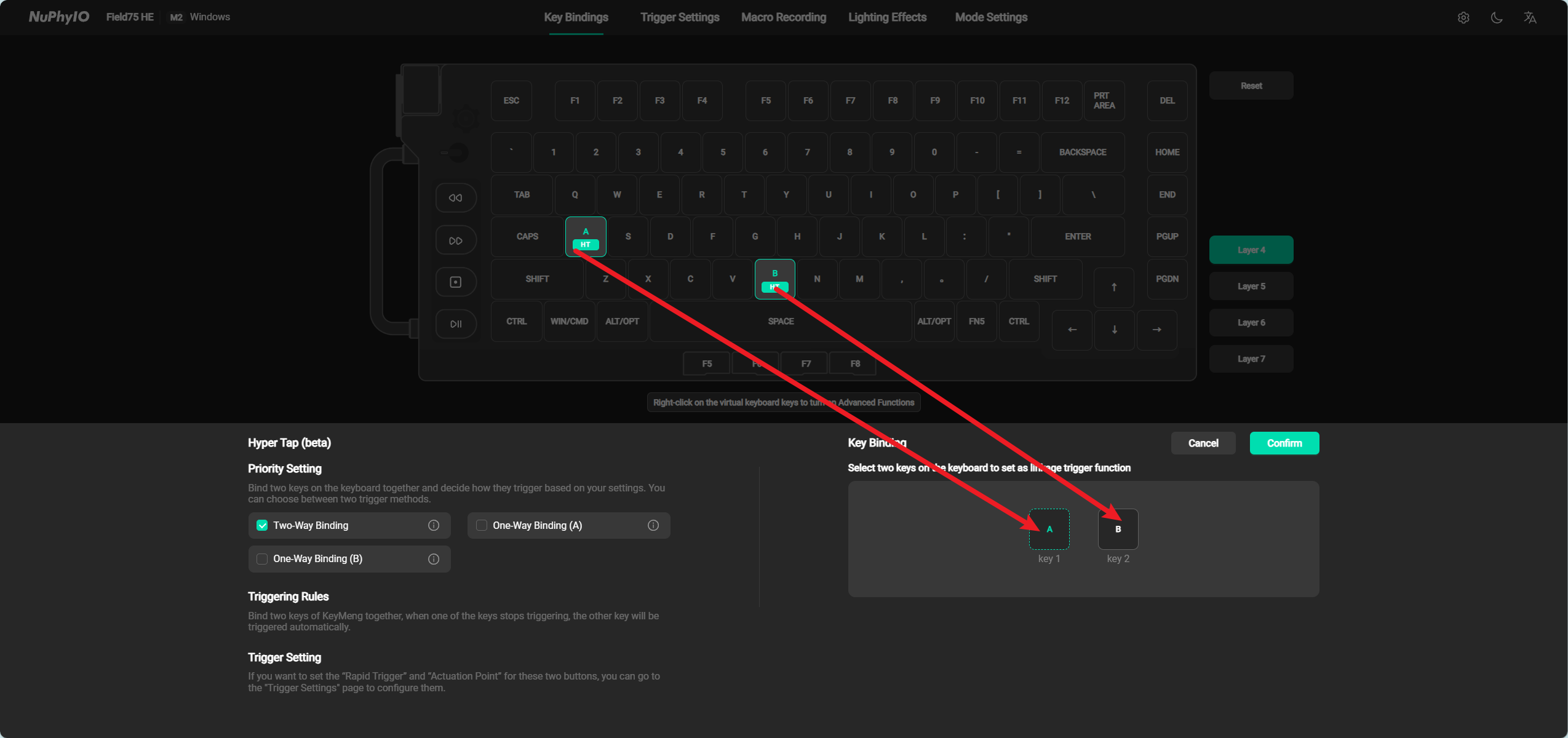
Hyper Tap (HT)
Under the Hyper Tap (HT) function, it is possible to bind two Switchs together, and when one Switch stops triggering, the other Switch will be automatically triggered.
The Hyper Tap(HT) function requires priority to be set first, and there are two priority options to choose from:
-
Bidirectional binding: When either Switch stops triggering, the other Switch is automatically triggered. For example, binding keys A and B as a Hyper Tap(HT) function, automatically triggering key B continuously when key A stops triggering, and automatically triggering key A continuously when key B stops triggering.
-
Unidirectional binding: When one of the two Switchs stops triggering, the other Switch is automatically triggered. For example, binding the A and B keys as a Hyper Tap(HT) function and setting a one-way binding of the A key will automatically trigger the B key continuously when the A key stops triggering, and will not automatically trigger the A key continuously when the B key stops triggering.
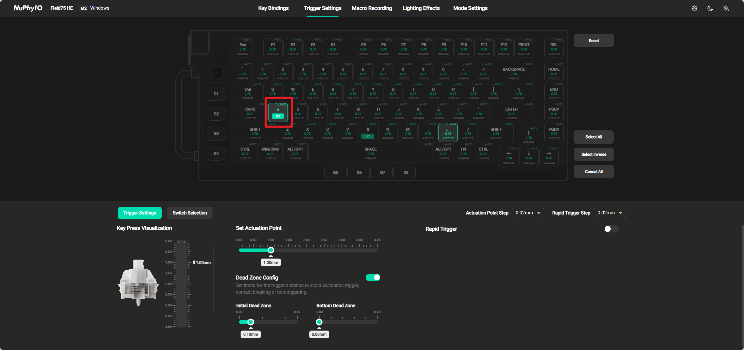
It should be noted that in the state of automatically triggering another Switch, as long as the Switch is raised another 0.05mm, the automatically triggered Switch will stop triggering.
After binding two Switchs, you can go to the Trigger Settings page to set their trigger parameters. The two Switchs bound together can modify all trigger parameters separately.
Trigger Settings Page
The virtual keyboard on this page displays the character arrangement order in the factory state of the keyboard. In order to facilitate users to accurately locate the position of the selected key, the keys on the virtual keyboard will not be affected by the key definition. For example, the upper left corner of the keyboard is the ESC key in its factory state. When the user customizes the key, they change it to the A key. After the change, pressing the ESC key actually displays the character A, but on the Trigger Settings page, it still displays ESC.
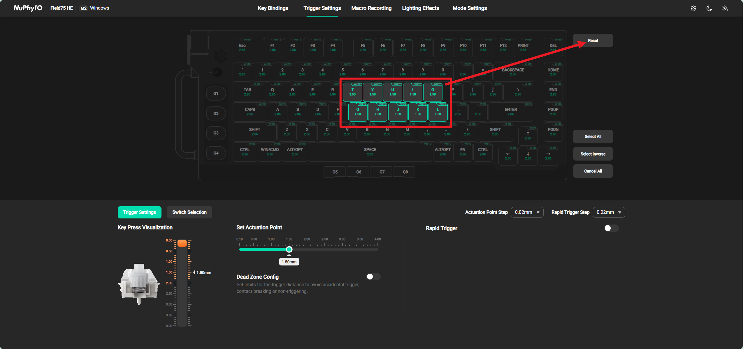
Reset
Clicking the Reset button Switch will restore the trigger parameters of the currently selected key, including Set Actuation Point, Dead Zone Config, and Rapid Trigger.
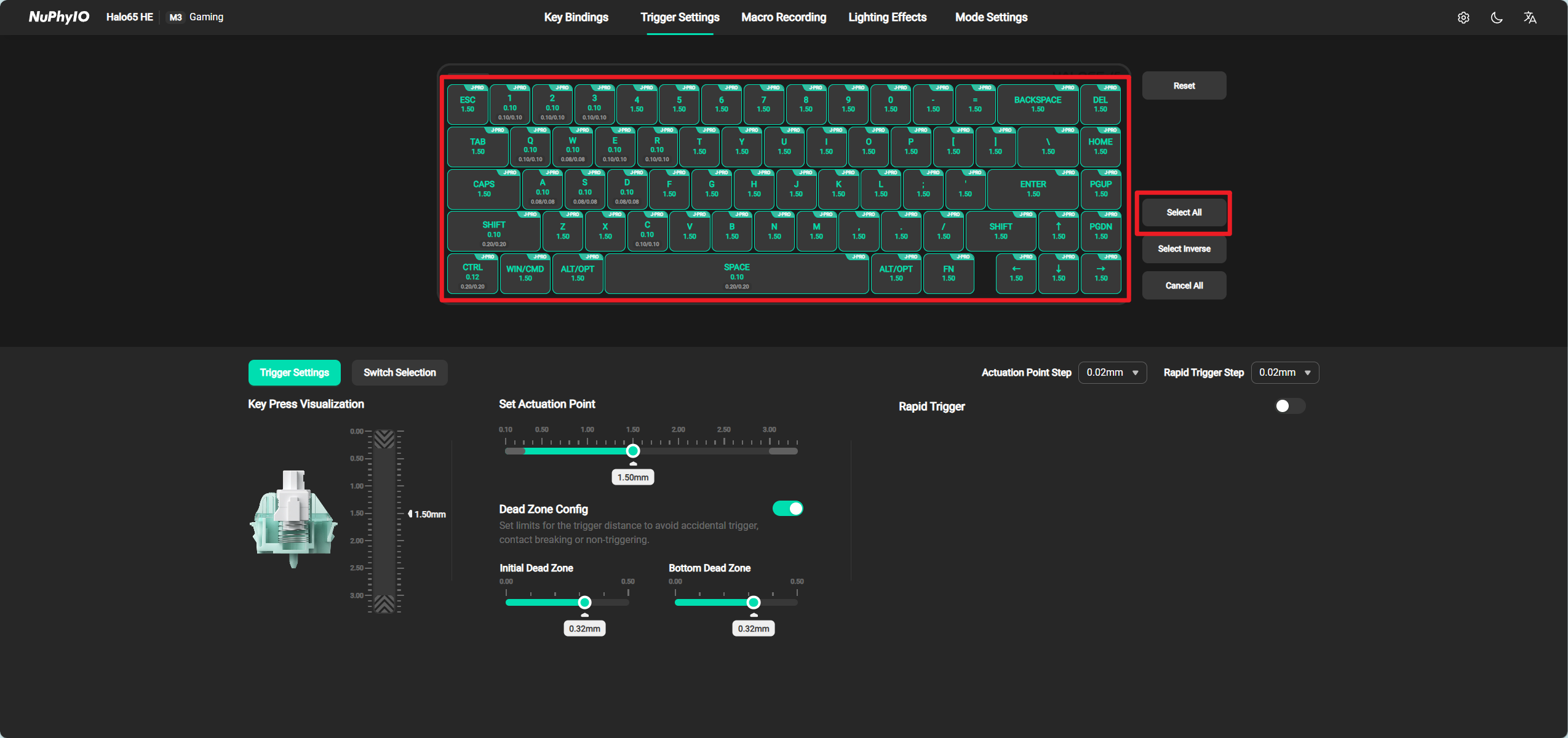
Select All
Click the Select All Switch to automatically select all Switchs. When a Switch is selected, the Trigger Settings below will display the parameters of the currently selected Switch. If the selected Switch parameters are different, the parameters of the last selected Switch will be displayed.
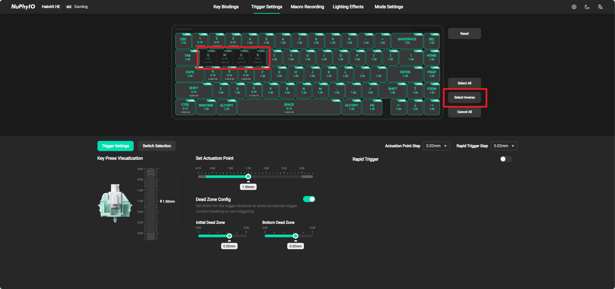
Select Inverse
Click the Select Inverse button to automatically select all unselected Switchs, and previously selected Switchs will be unselected.
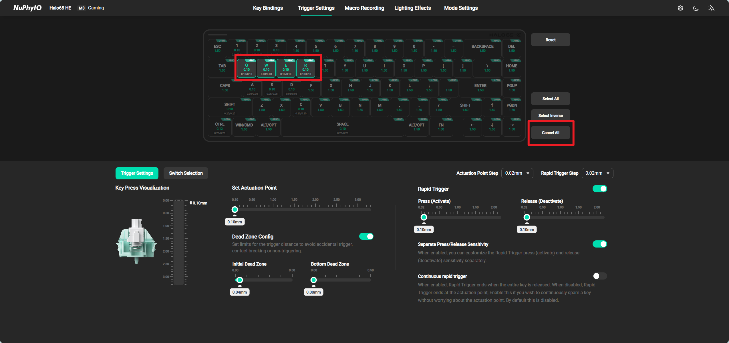
Cancel All
Click the Cancal All button to automatically uncheck all Switchs.
Trigger Settings
You can modify the parameters of Set Actuation Point, Dead Zone Config, and Rapid Trigger. for all selected keys.
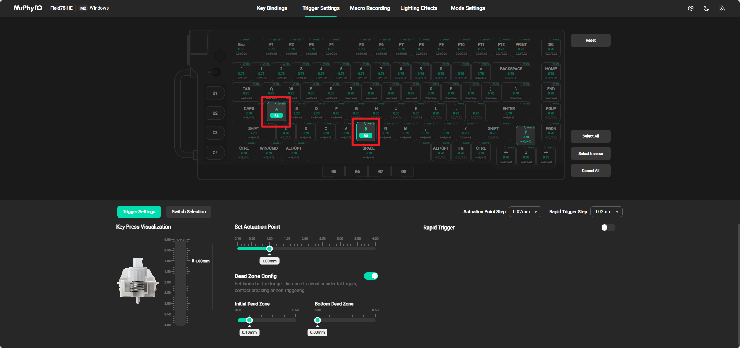
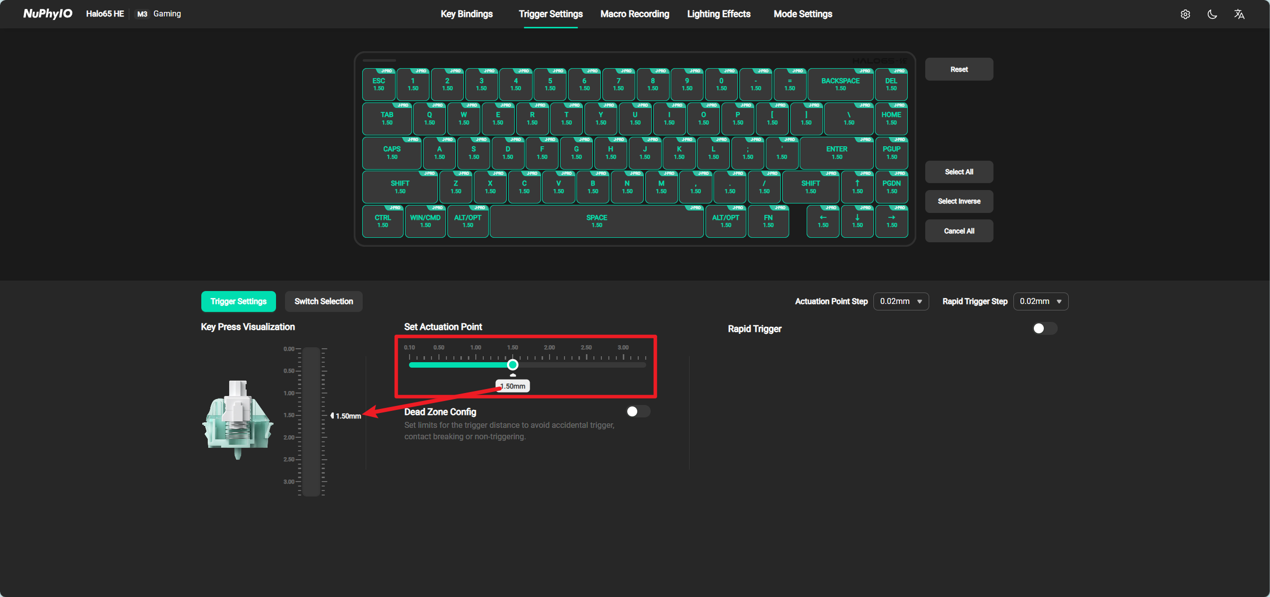
Set Actuation Point
The meaning of Actuation Point is: how many millimeters will the currently selected key continue to trigger after being pressed? For example, if the A key is selected and its trigger key stroke is adjusted to 1mm, then when the A key on the keyboard is pressed ≥ 1mm, the A key will continue to trigger.
When adjusting the Actuation Point, the scale line on the left side of the Switch will display the current position of the Actuation Point in real time.
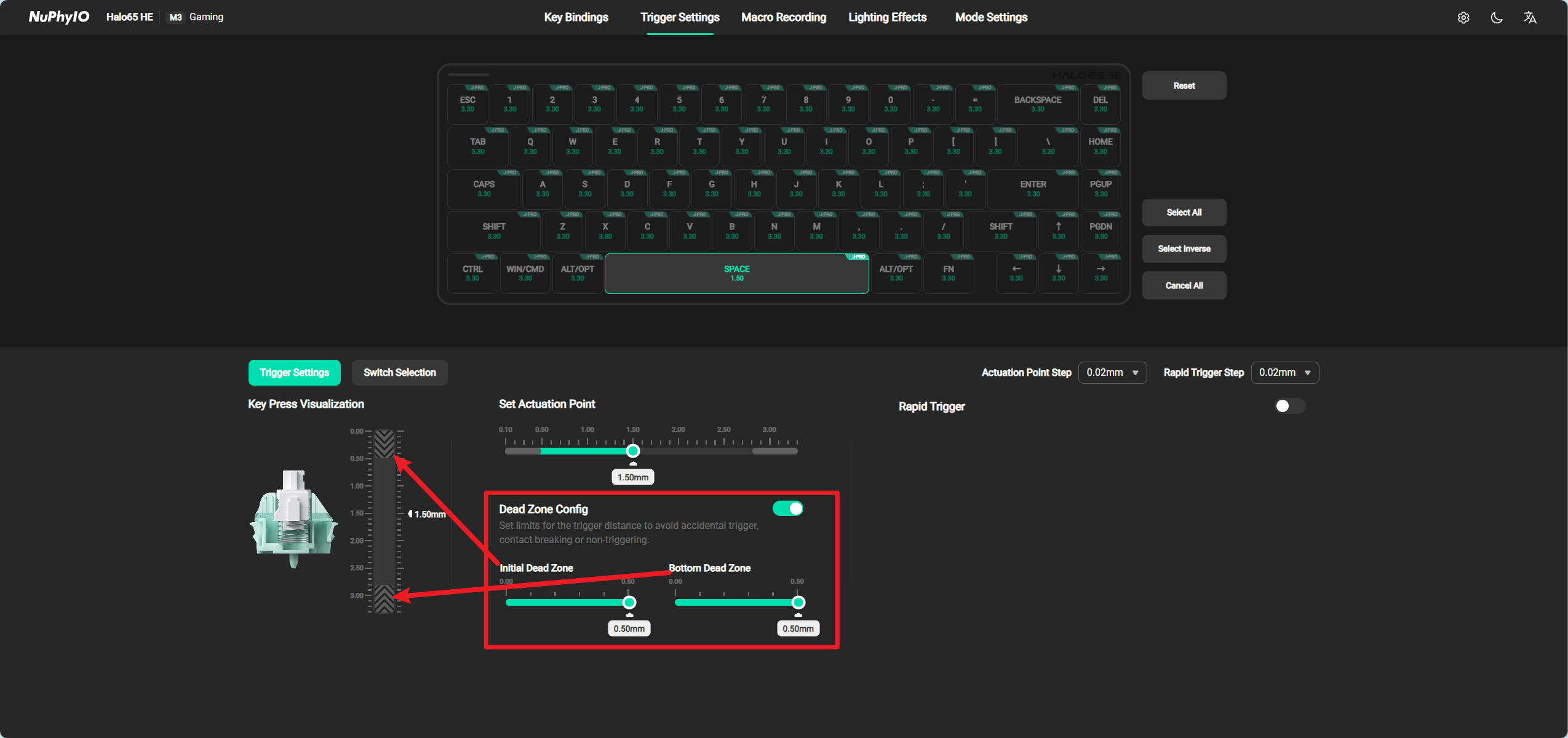
Dead Zone Config
Support limiting the Actuation Point of the Switch to avoid accidental, disconnected, and non triggering phenomena. The Initial Dead Zone is to limit the initial key travel of the Switch, and the Bottom Dead Zone is to limit the bottom key travel of the Switch.
For example, adjusting the Initial Dead Zone to 0.5mm, when pressing this Switch, the Switch will not trigger within the range of 0mm to 0.5mm (not affected by the Actuation Point and Rapid Trigger), to avoid accidentally touching this Switch.
For example, if the Bottom Dead Zone is adjusted to 0.5mm, and the trigger key stroke range of this Switch is 0.1mm to 3.3mm, when this Switch is pressed, the Switch will trigger within the range of 2.8mm (i.e. 3.3-0.5mm) to 3.3mm (not affected by the Actuation Point and Rapid Trigger), avoiding the Switch from breaking or not triggering.
When the Dead Zone Config is turned off, it means that the currently selected Switch is in the 0 Dead Zone state and will not have any restrictions on triggering behavior.
When adjusting the Dead Zone Config, the scale line on the left side of the Switch will display the current range of the dead zone in real time.
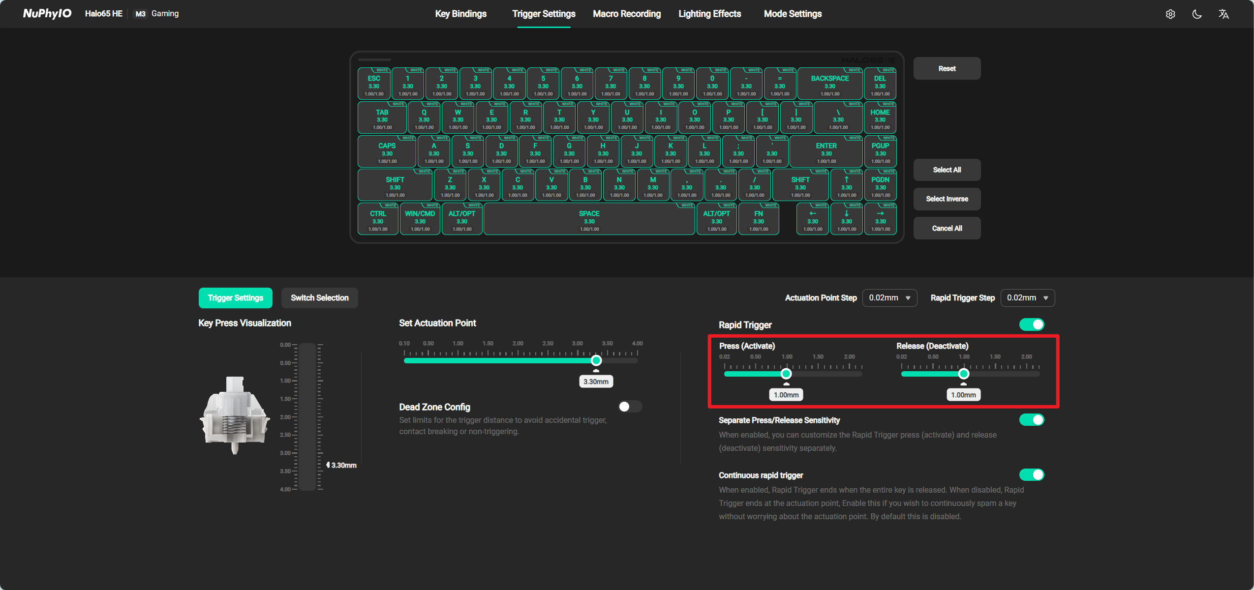
Rapid Trigger(RT)
Support setting the currently selected Switch, and after triggering, determine how much distance to lift to stop triggering and how much distance to press to trigger again (provided the Switch is not fully lifted).
For example, when the Actuation Point of the selected Switch is set to 2mm and the Release(Deactivate) is set to 1mm, the Switch will continue to trigger when pressed 4mm. At this time, as long as the Switch is lifted 1mm, it will stop triggering (if the Rapid Trigger is not turned on, it needs to be lifted to 2mm of this Switch to stop triggering). A Switch set to **Release (Deactivate)**will stop triggering faster.
For example, when the Actuation Point of the selected Switch is set to 2mm and the Press (Activate) is set to 1mm, the Switch will continue to trigger when pressed 4mm. At this time, it will stop triggering when lifted to 0.1mm, and it will trigger again when pressed 1mm again (if the Rapid Trigger is not turned on, it needs to be pressed to 2mm of this Switch before it will trigger again). A Switch set to Press (Activate) will trigger again faster.
It is worth noting that Rapid Trigger is a relative value. Setting Release(Deactivate) to 1mm means that the Switch stops triggering after being lifted 1mm from its current position (if the current Switch is pressed 2mm, it stops triggering at 1mm; if the current Switch is pressed 3mm, it stops triggering at 2mm).
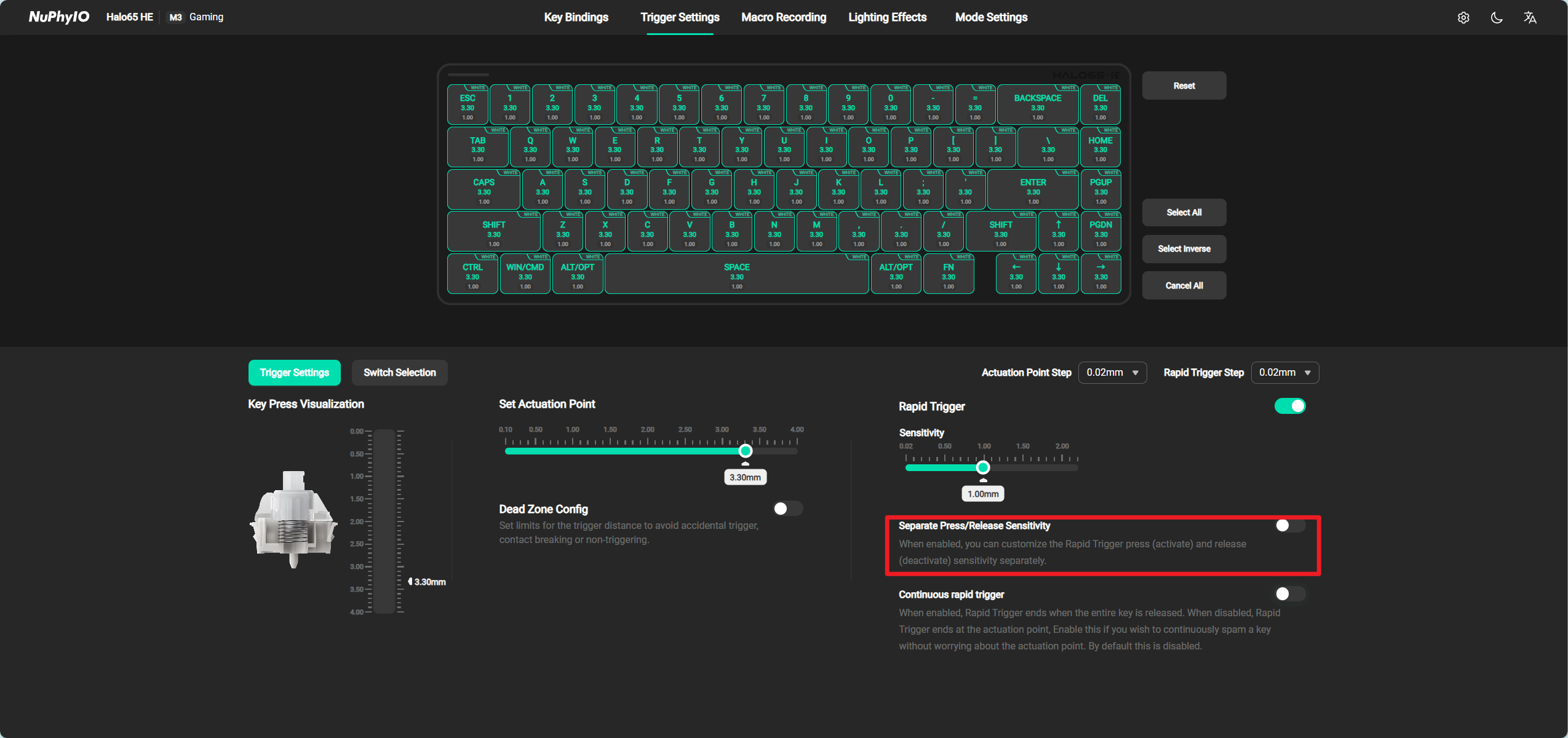
Separate Press/Release Sensitivity
When this setting is turned off, Press (Activate) and Release(Deactivate) are adjusted simultaneously. When this setting is turned on, Press (Activate) and Release(Deactivate) are adjusted separately.
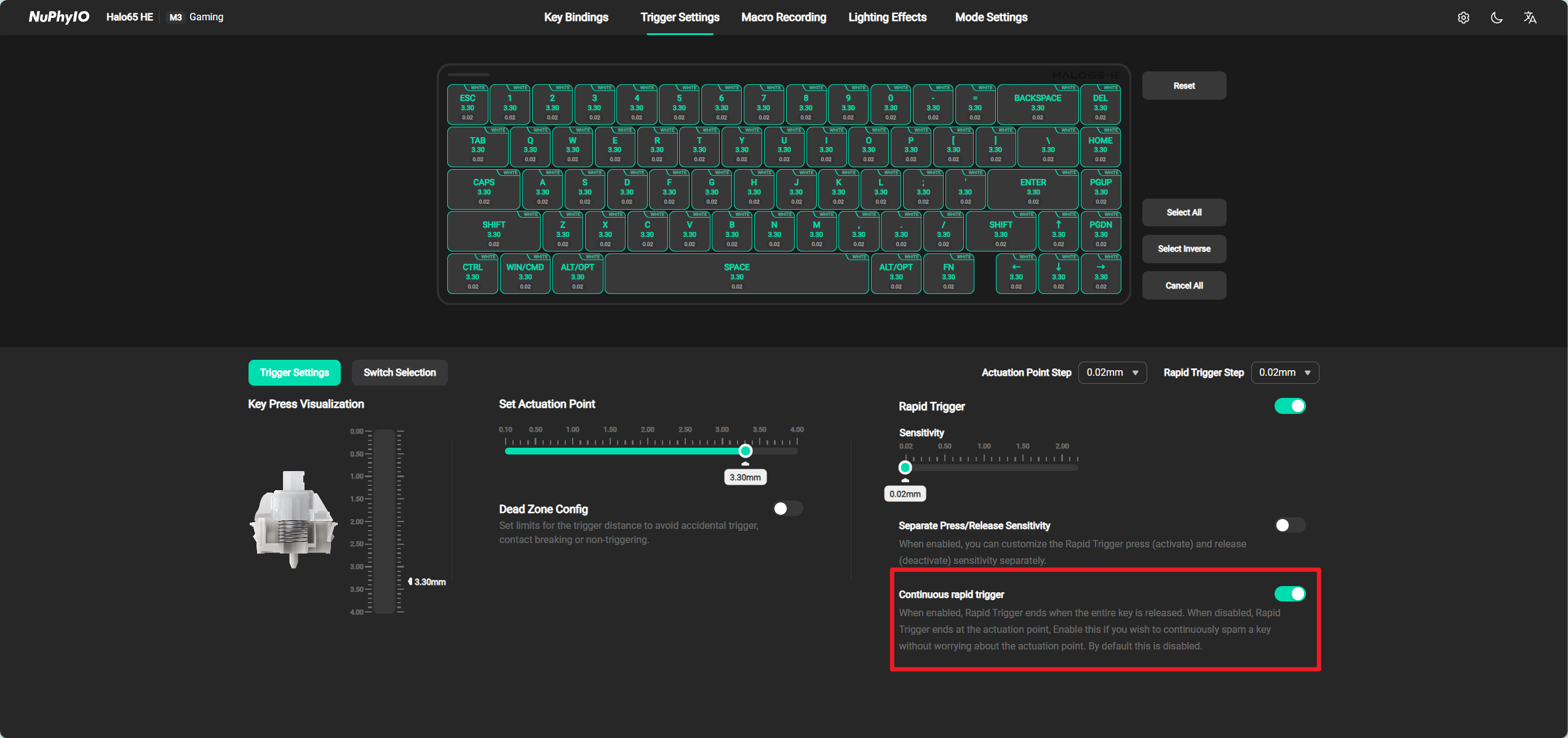
Continuous Rapid Trigger
When this setting is turned on, the Rapid Trigger will only terminate when the Switch is fully released.
When this setting is turned off, the Rapid Trigger only takes effect below the Actuation Point.
For example, when the selected Switch's Actuation Point is set to 2mm, the trigger key stroke range of this axis body is 0.1mm to 4.0mm. When the Continuous Rapid Trigger is turned off, the Rapid Trigger will only take effect between 2.0mm and 4.0mm. When the Continuous Rapid Trigger is turned on, the Rapid Trigger will take effect between 0.1mm and 4.0mm.
Macro Recording
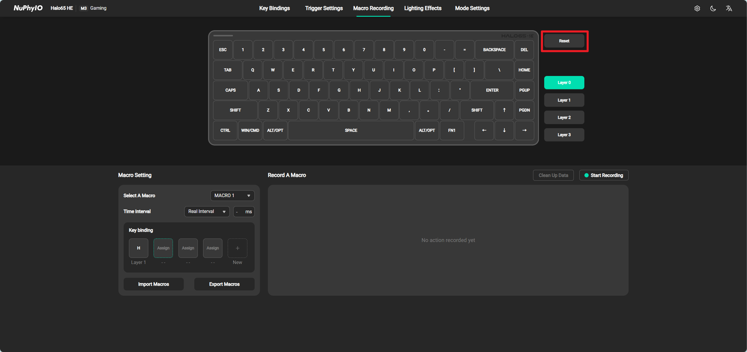
Reset
Click the Reset button Switch to restore the factory settings of all keys in the current level (including custom key changes).
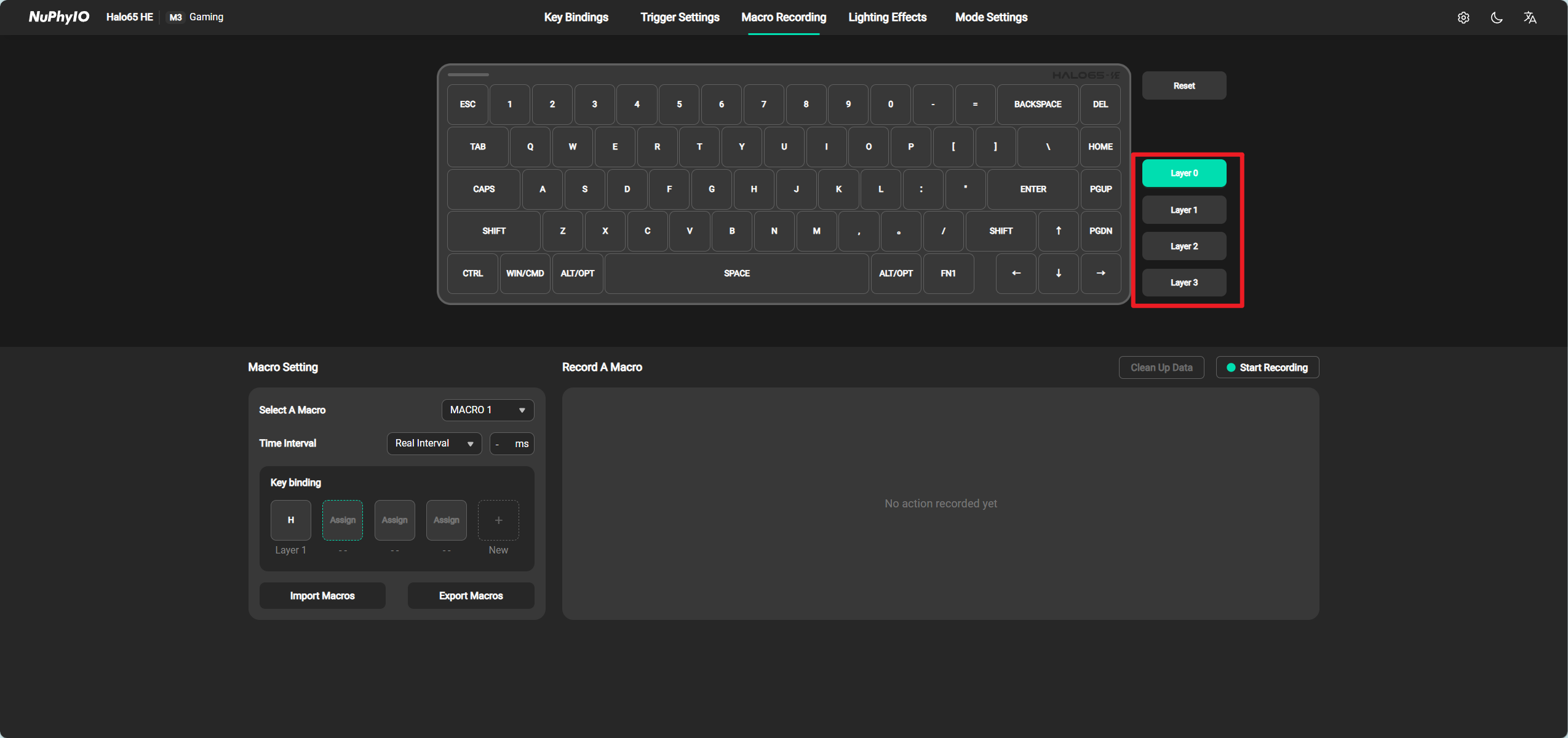
Layer Switching
Clicking on a button at a certain Layer will display the buttons bound to that Layer. Each level has a corresponding number, and you need to hold down the corresponding FN key to use the keys bound to this Layer. For example, if you have bound the A key at a certain position in Layer 5, you must hold down FN5 and then press the key at the position where the A key is located to trigger the A key function.
It should be noted that each mode has a default Layer, which is arranged above all Layer.
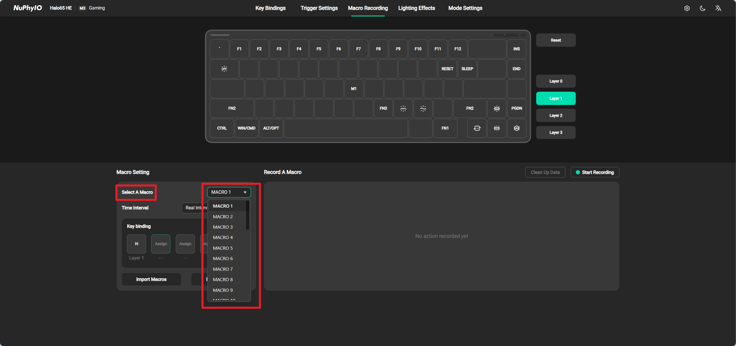
Macro Setting
Select A Macro
Due to the limitation of keyboard storage capacity, each mode has a fixed 32 macro keys available for modification and binding.
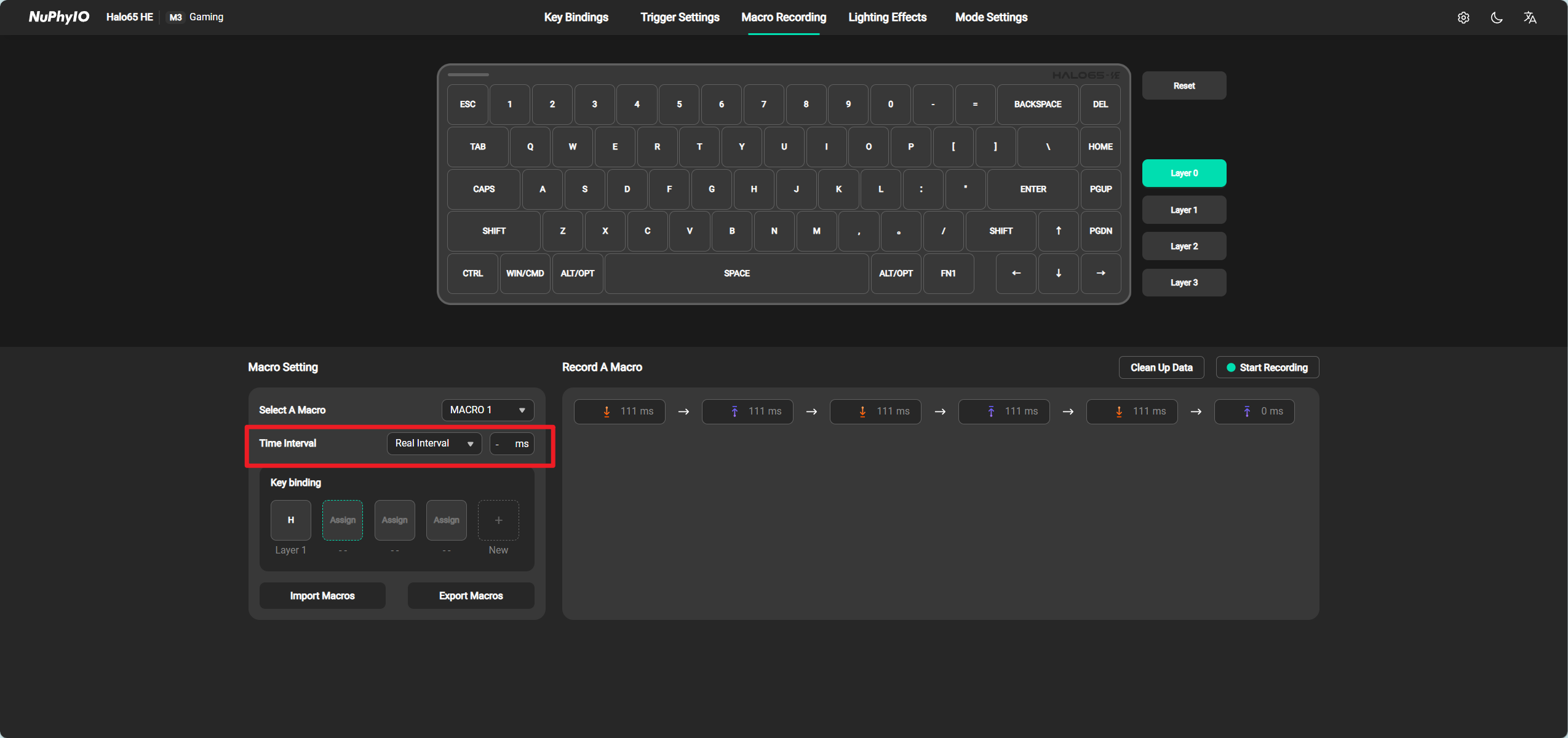
Time Interval
When selecting Real Interval, the program will enter the actual interval between two recorded button operations.
When selecting Default Interval, the program will insert the set time interval between two operations.
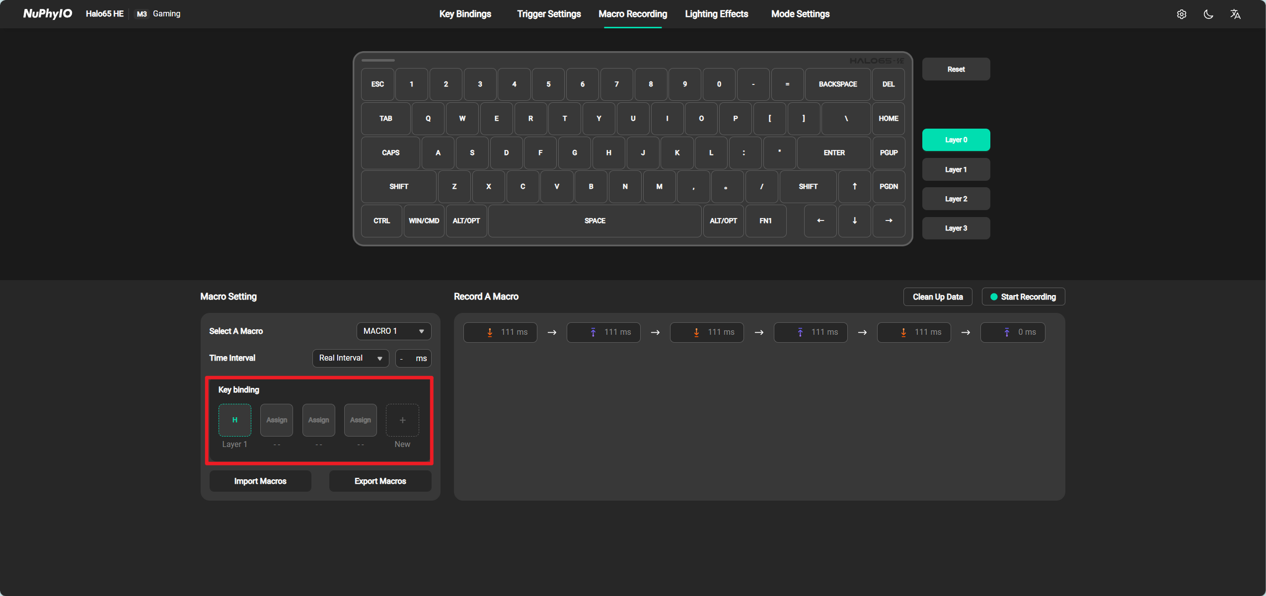
Key Binding
Supports binding this macro to any key on the keyboard, but each key on the keyboard can only be bound to one macro at a time. After binding, it supports deleting or adding binding buttons.
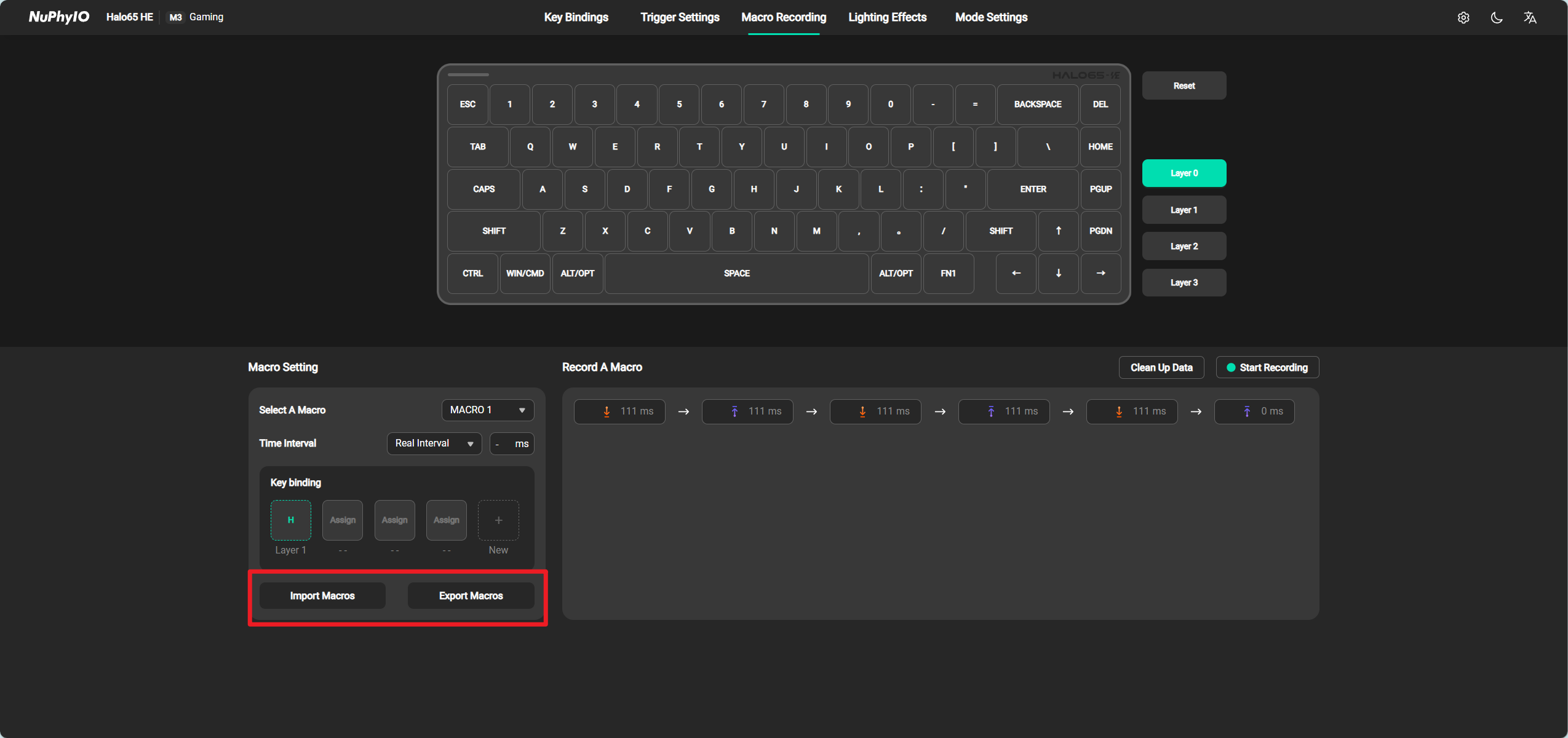
Import/Export Macros
Support exporting or importing the currently selected macro to overwrite the current macro.
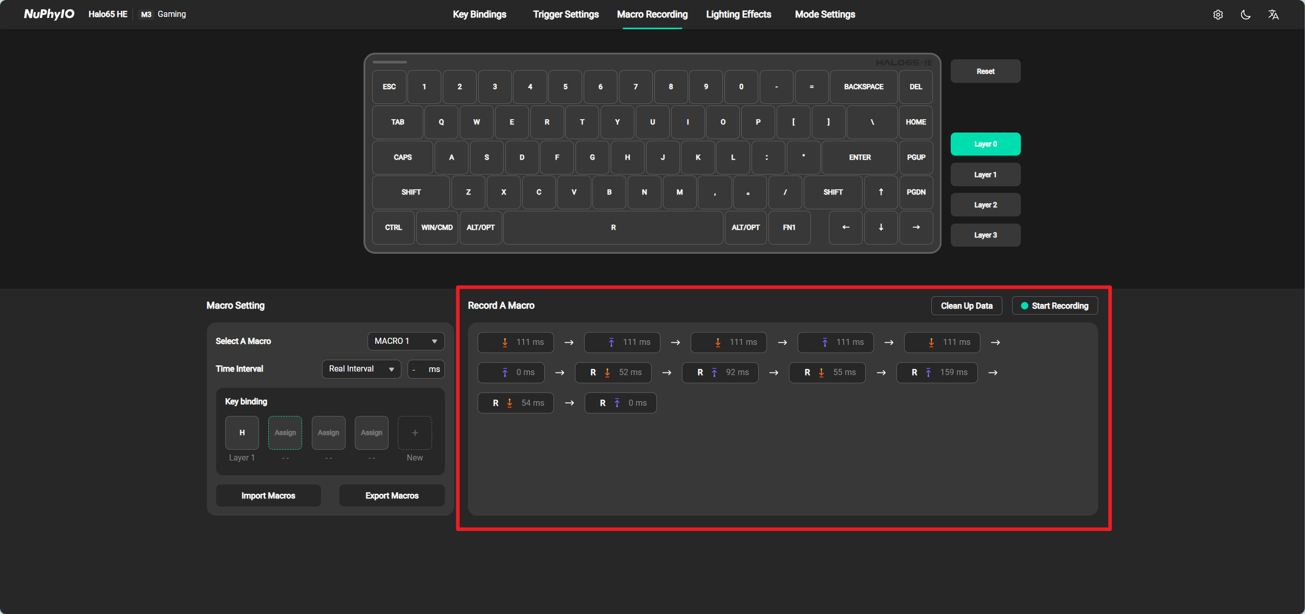
Record A Macro
Support one click clearing of all recorded macros.
After clicking on Start Recording, press the keys on the keyboard to enter all the pressing operations. At present, it is not supported to enter keys bound with advanced functions. When a key bound with advanced functions is pressed, the default factory function of the key is entered.
After recording is completed, it supports deleting, dragging to adjust the operation position, and clicking to modify the operation delay.
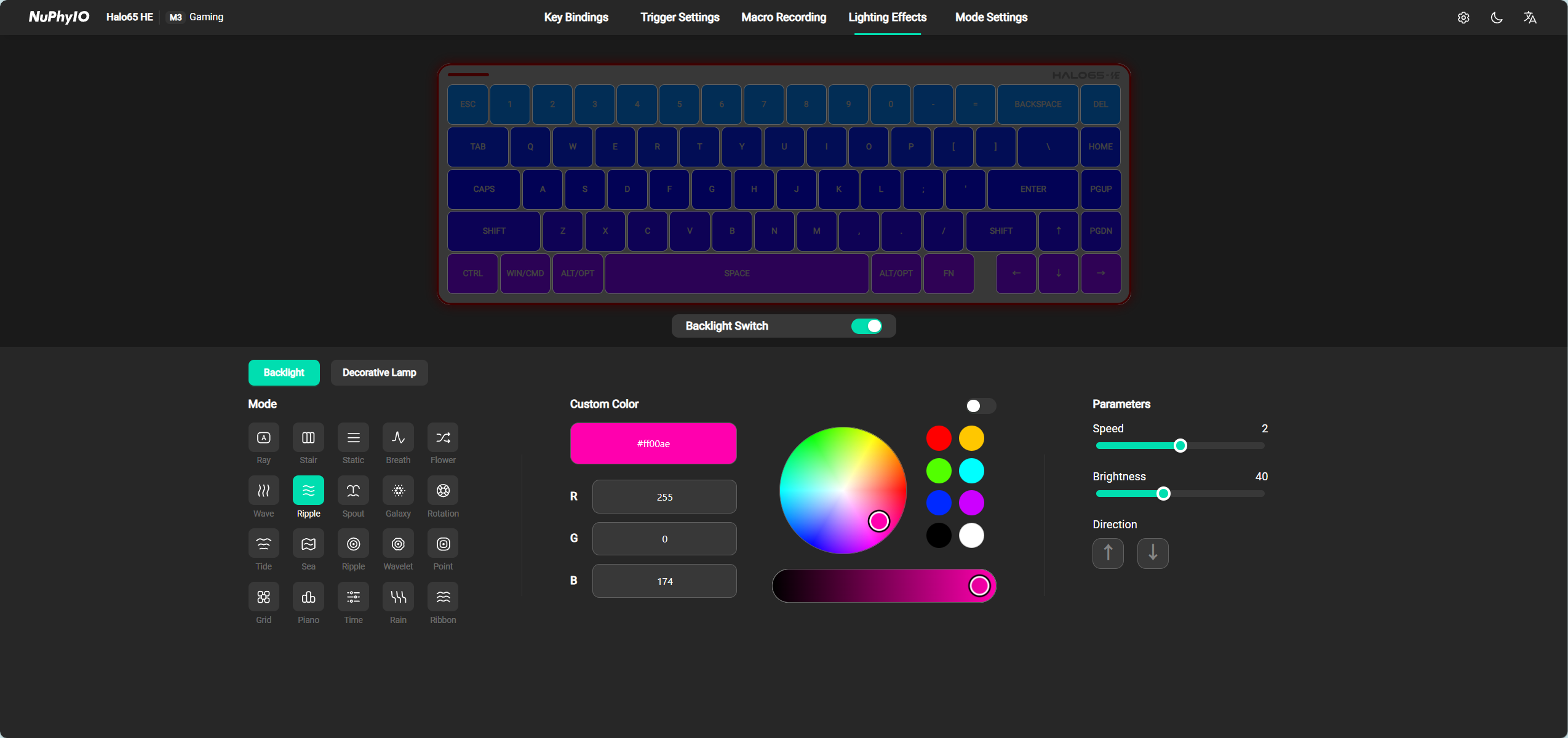
Lighting Effects
On the Lighting Effect page, it supports modifying the color, direction, speed, and brightness of backlight, strip lights, and decorative lights (some light effects may not be able to change color, direction, and speed due to different light effects), and supports turning on/off backlight, strip lights, and decorative lights.
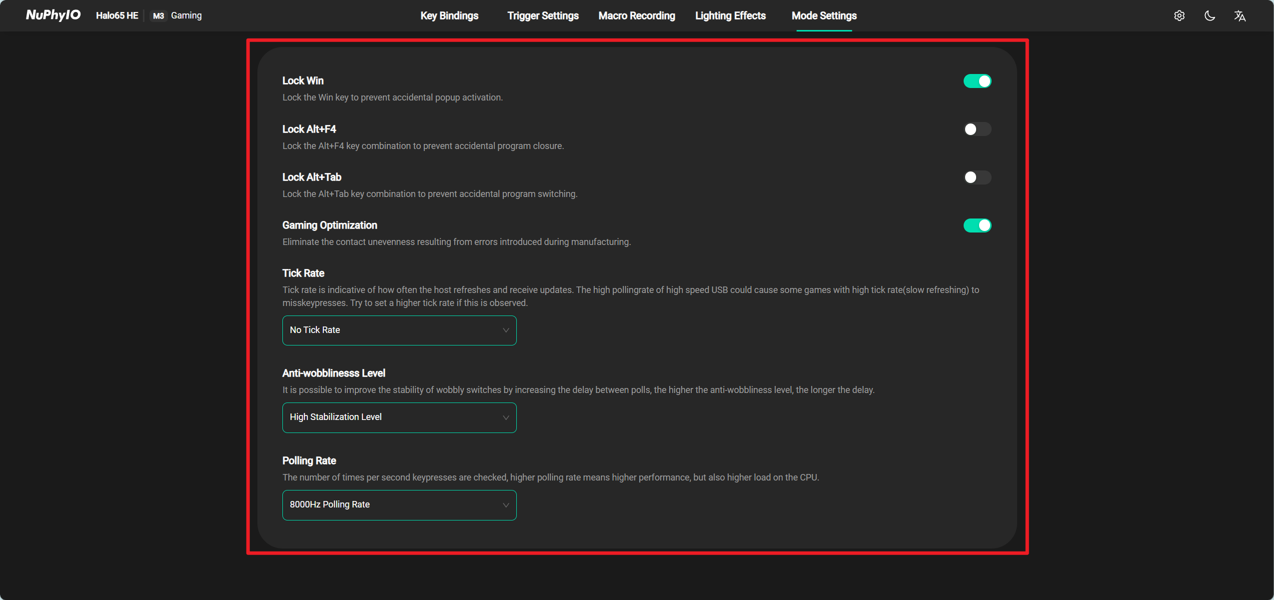
Mode Settings
Set various parameters for the current keyboard mode.
Lock WIN
In some games, accidentally touching this button will exit the game. When the Lock WIN switch is turned on, pressing any WIN button in this mode will not take effect.
Lock ALT+F4
In some games, the effect of this combination key is to exit the game. When the Lock ALT+F4 switch is turned on, this combination key will not take effect in this mode.
Lock ALT+TAB
In Windows mode, the effect of this key combination is to switch programs. When the Lock ALT+TAB switch is turned on, this key combination will not take effect in this mode.
Gaming Optimization
Due to tolerances that may occur during the manufacturing process of the Switch, their key stroke range may not be within the standard range. For example, if the standard key stroke of a certain shaft is 0 to 4mm, some actual key strokes may be 0 to 3.8mm and some actual key strokes may be 0 to 4.2mm in a pile of these shafts.
When Gaming Optimization is turned on, the program will detect the voltage of all axis bodies when they touch the bottom, dynamically adjust their key stroke range, and avoid problems such as disconnection and non triggering.
Trick Rate
Due to the keyboard reporting actions being too fast, some computers with insufficient performance may not be able to recognize all pressed keys or may miss recognizing pressed keys. Especially in some games, if the interval between button press and release actions is too short, it may not be responded to.
If the computer cannot recognize all pressed keys or misses recognizing pressed keys, it is recommended to first adjust the Trick speed to 60, and if it still occurs, then adjust it to 30.
Under normal circumstances, there is no need to adjust this parameter. Simply select No Trick Rate.
Trick speed may potentially increase keyboard latency.
Anti-Wobblinesss Level
Due to the different stability of different Switch, the keyboard can reduce the double-click problem caused by the instability of Switch by increasing the delay, and the higher the anti shake level, the higher the delay.
Polling Rate
The speed of reading keyboard key operations on the keyboard increases with higher numerical values. Increasing the return rate will increase the burden on the system CPU and increase the power consumption of the keyboard.
Keyboard Settings Page
Keyboard Settings
Auto Select All
After turning on Auto Select All, when all Switch types on the keyboard are the same, the Trigger Settings page will automatically select all keys.
Auto Sleep
After turning on Auto Sleep, the keyboard will automatically turn off the lights and enter sleep mode when it is in an inactive state (approximately 6 minutes later).
Export Configurations
Merge and export all saved modes in the keyboard into one configuration file.
Import the profiles of all modes into one single file
Import the configuration file and overwrite all saved modes on the current keyboard.
Reset Keyboard
Resetting the keyboard will restore it to factory settings and delete all user configurations. Please proceed with caution.
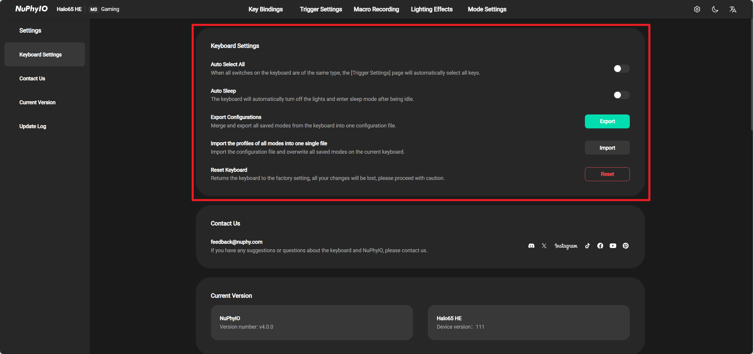
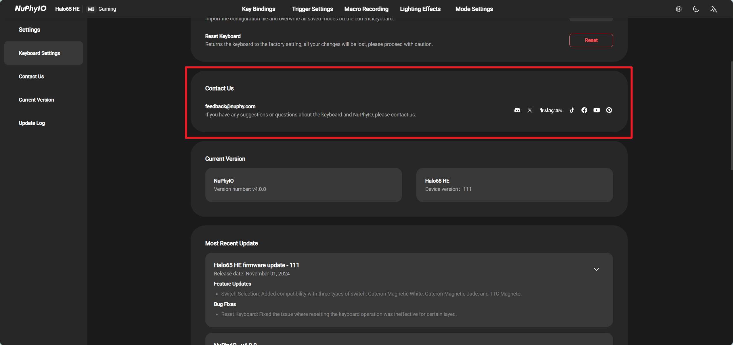
Contact Us
If you have any questions or suggestions regarding the keyboard or drivers, please contact us through feedback@nuphy.com or contact us through the customer service of the platform you ordered.
If you want to get more keyboard information, please follow our account or join our community through the social platforms listed in the driver.
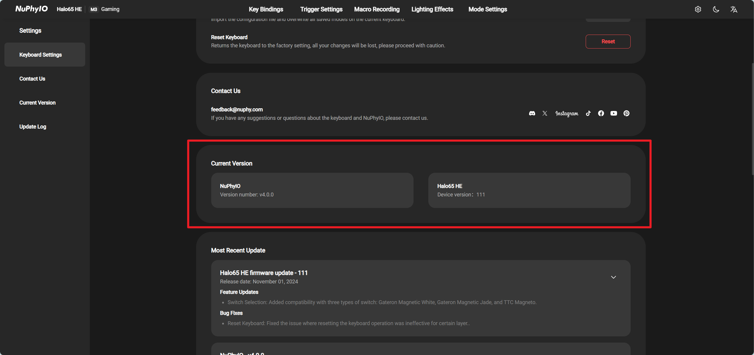
Current Version
Here are the version numbers of the drivers and currently connected devices listed.
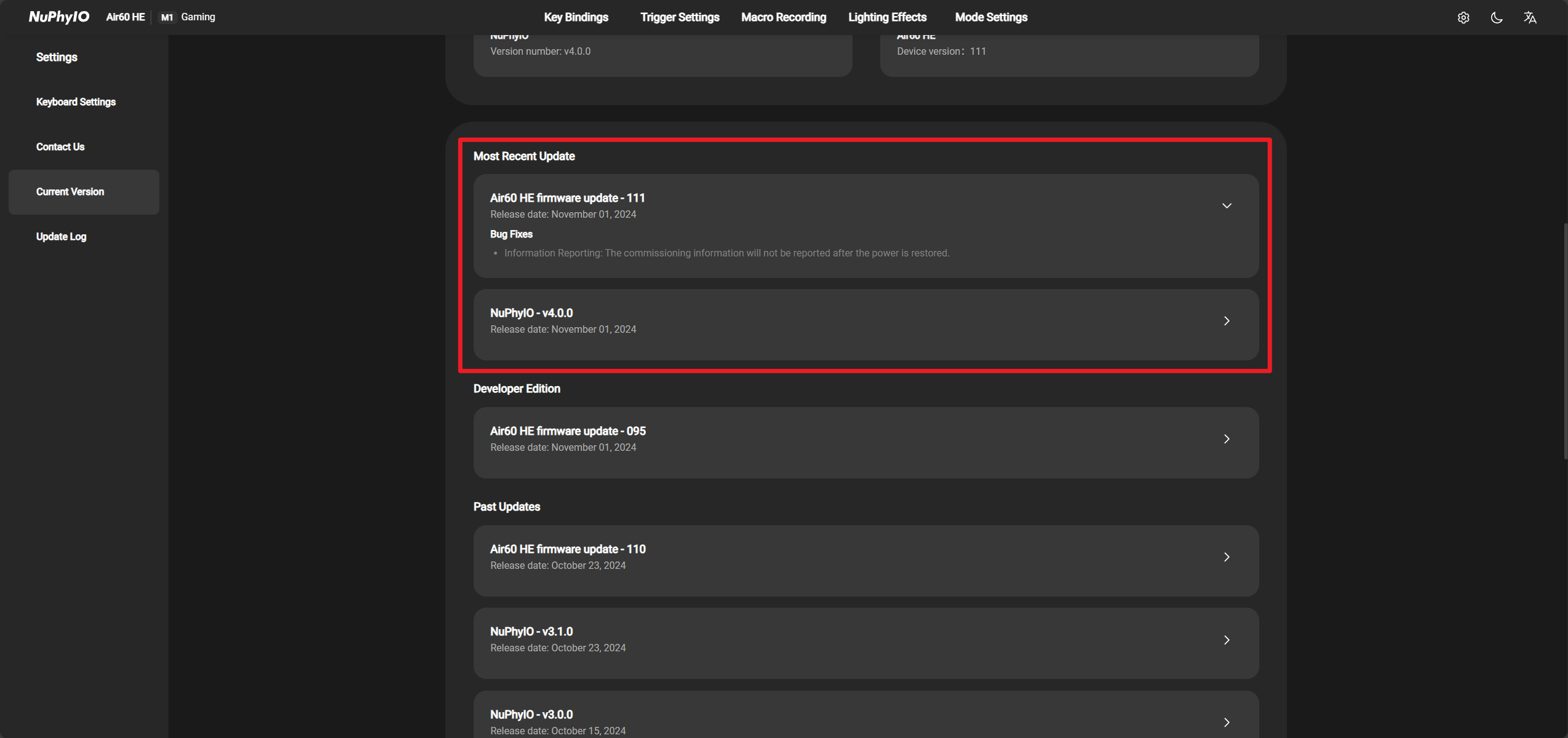
Update Log
Most Recent Update
Here are the latest updated versions of the drivers and currently connected keyboards listed.
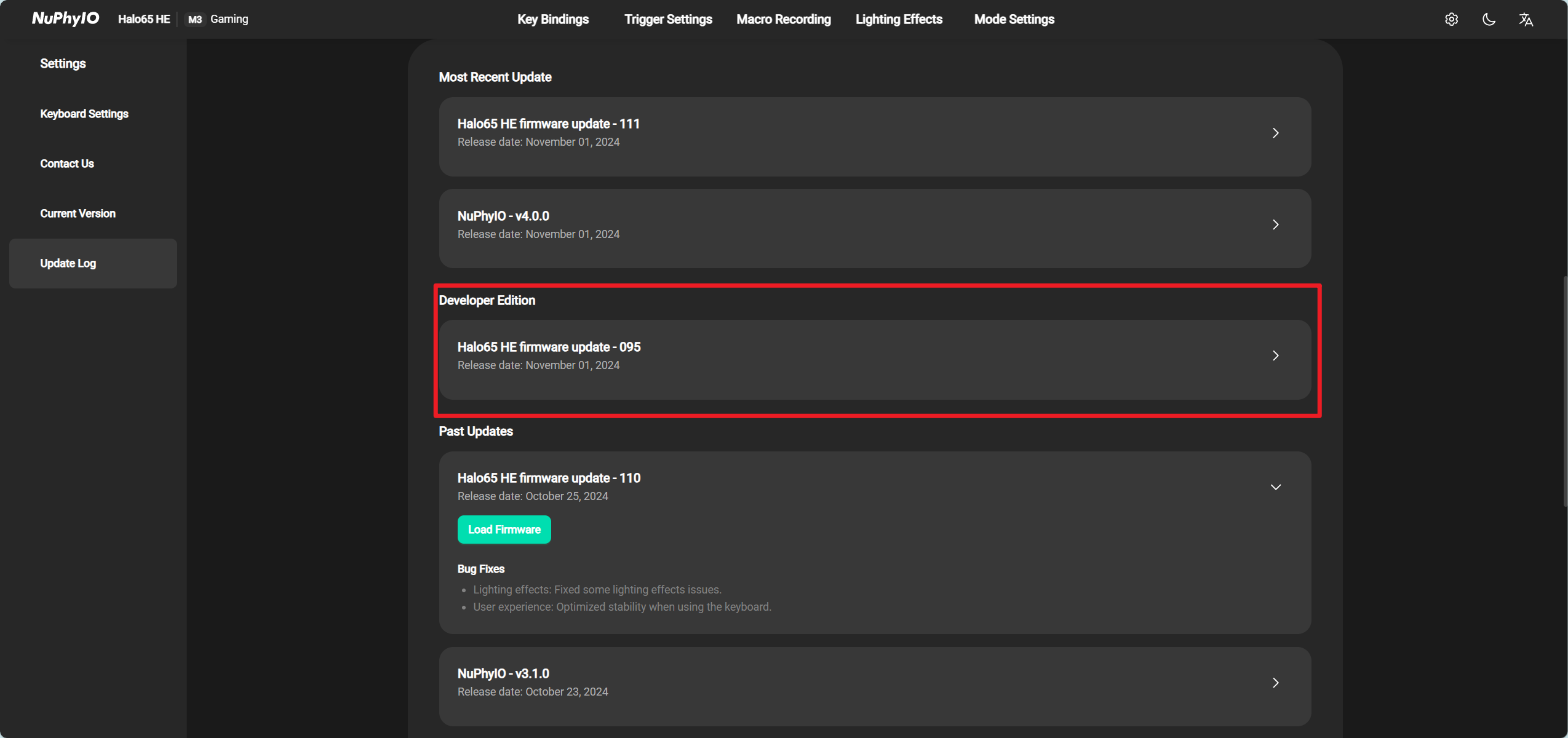
Developer Edition
For the convenience of internal coordination and development, we have added a Developer Edition to this module to announce the firmware updates that will be released soon.
If you want to experience the latest firmware, you can try downloading it, but the developer version firmware is unstable and prone to problems.
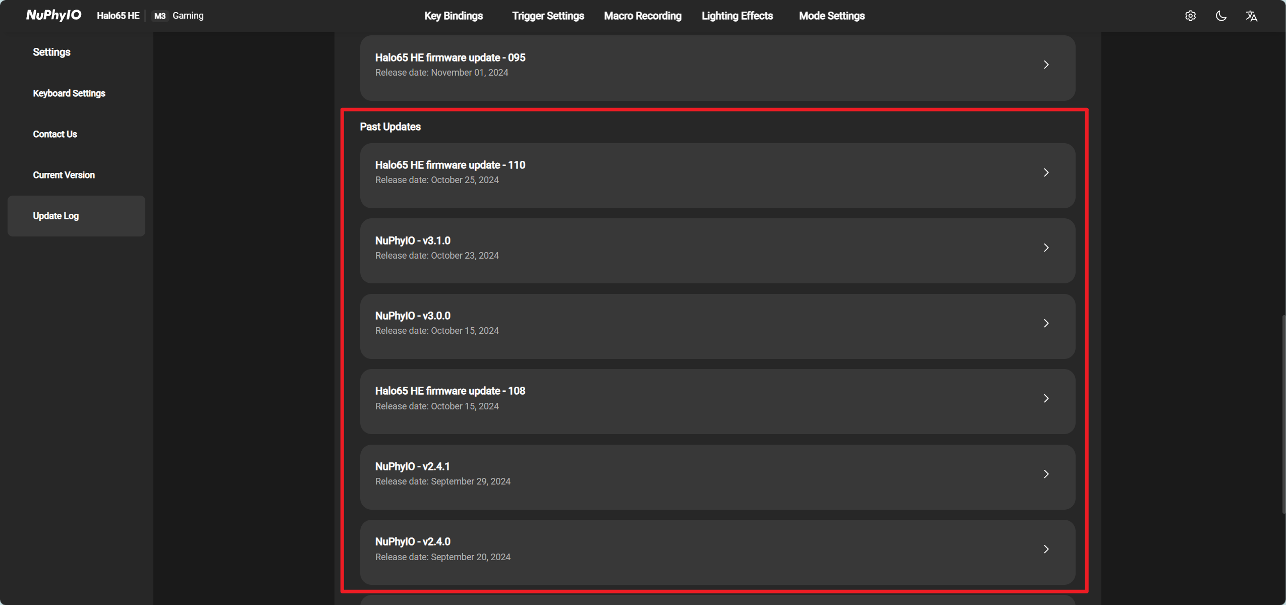
Past Updates
Here is a list of drivers and historical versions of the currently connected keyboard, supporting rollback of the two most recently released firmware versions.
Still have questions or need help?
Please feel free to contact the customer service or feedback@nuphy.com contact us.